Anchor node deployment method for dynamic underwater environment

An underwater environment, anchor node technology, applied in the direction of advanced technology, network planning, electrical components, etc., can solve the problems of low network coverage in the monitoring area, and achieve the goal of improving network coverage, extending operating time, and improving network coverage. Effect

Inactive Publication Date: 2019-12-13
TIANJIN UNIV
View PDF3 Cites 1 Cited by
  • Summary
  • Abstract
  • Description
  • Claims
  • Application Information

AI Technical Summary

Problems solved by technology

[0004] Aiming at the problem of low network coverage in the monitoring area caused by the water flow in dynamic waters, the present invention proposes a distributed underwater wireless sensor network anchor node deployment strategy based on virtual force

Method used


Image

  • Anchor node deployment method for dynamic underwater environment
  • Anchor node deployment method for dynamic underwater environment
  • Anchor node deployment method for dynamic underwater environment

Examples


Embodiment Construction

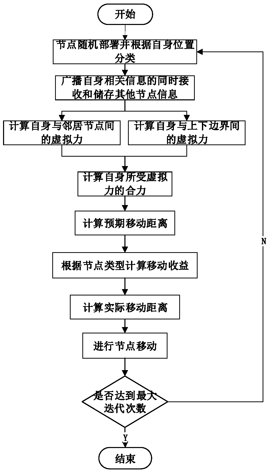
[0029] The specific manner, structure, features and functions of the node deployment strategy designed according to the present invention are described in detail below in conjunction with the accompanying drawings.

[0030] The present invention provides an anchor node deployment method for a dynamic underwater environment, comprising the following steps:

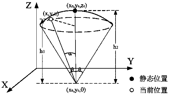
[0031] Such as figure 1 As shown; Step 1: Nodes are randomly deployed to the water surface of the monitoring area, and randomly sink to the upper half of the monitoring area. Each node calculates its own coordinates according to the position of its seabed anchor, water depth, water flow size and water flow direction, and judges the distance from itself to the border of the surrounding monitoring area, excluding the upper and lower boundaries. If the distance between the two is less than the optimal boundary distance d ob , then divide itself into a boundary node; otherwise, divide it into a normal node. At the same time,...


PUM


Abstract

The invention discloses an anchor node deployment method for a dynamic underwater environment. The anchor node deployment method comprises the following steps: 1, randomly deploying underwater nodes and dividing common nodes and edge nodes according to the positions of the underwater nodes to establish an anchor node model; setting N to be equal to 0; 2, broadcasting related information of each node in the anchor node model, and receiving and storing information of other nodes at the same time; 3, calculating the resultant force of the virtual force borne by each node; 4, calculating an expected moving distance between each common node and the boundary node; 5, calculating the mobile income according to the type of the node; 6, calculating the moving distance of each node along the anchorchain; 7, judging whether each node meets the condition that N is greater than or equal to 45, and if yes, exiting the program; otherwise, returning to the step 1, and enabling N to be equal to N + 1;the invention provides a mobile benefit function which comprehensively considers the node density, the node residual energy and the node moving effect, so that the unnecessary movement of the node isreduced, the node residual energy is balanced, and the purpose of reducing and balancing the energy consumption is achieved.

Description

technical field [0001] The invention relates to the technical field of underwater wireless sensor networks, in particular to an anchor node deployment method for dynamic underwater environments. Background technique [0002] As a convenient tool for understanding and understanding the ocean, the underwater wireless sensor network can enable people to obtain more ocean information, improve the ability to monitor and predict the ocean environment, and help people deal with ocean emergencies. It has a wide range of applications, such as marine information collection, environmental monitoring, deep-sea exploration, disaster prediction, auxiliary navigation, distributed tactical monitoring, etc. The premise of the above application is effective environmental monitoring of relevant sea areas and effective coverage of relevant sea areas by using underwater wireless sensor network nodes. Therefore, the deployment strategy of underwater sensor network nodes needs to increase the res...

Claims


Application Information

Patent Timeline
Patent Type & Authority Applications(China)
IPC IPC(8): H04W16/18H04W24/02H04W24/06H04W84/18
CPCH04W16/18H04W24/02H04W24/06H04W84/18Y02D30/70
Inventor 刘春凤邱铁赵昭曲雯毓
Owner TIANJIN UNIV
Why Eureka
Try Eureka