
vane pump

A technology of vane pumps and pump chambers, applied to pumps, pump components, rotary piston pumps, etc., can solve problems such as deterioration of vehicle installation, achieve good pump efficiency, prevent instantaneous leakage, and reduce leakage

Active Publication Date: 2021-08-24
MIKUNI CORP
View PDF8 Cites 0 Cited by
  • Summary
  • Abstract
  • Description
  • Claims
  • Application Information

AI Technical Summary

Problems solved by technology

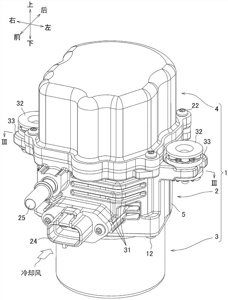
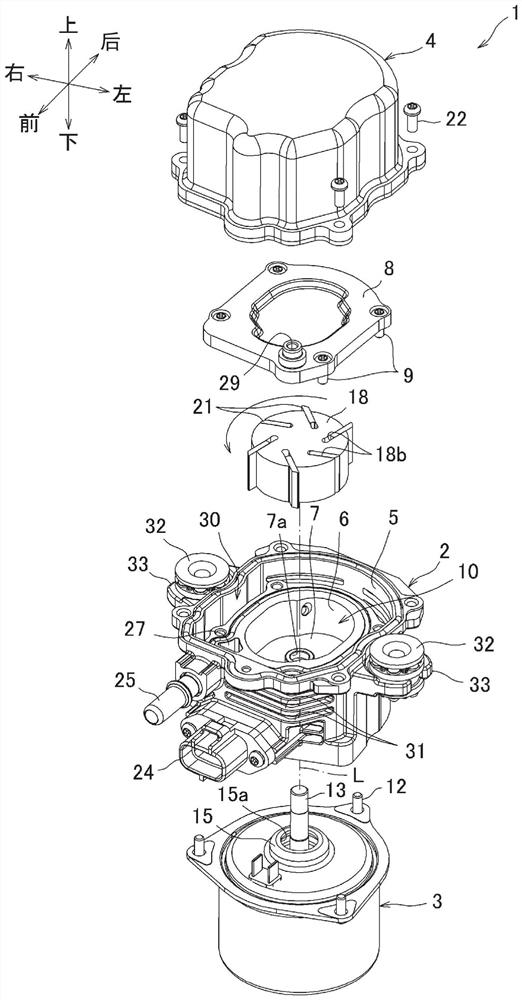
[0003] The capacity (fluid discharge rate) of the vane pump depends on the change in the volume of the pump chamber, but the increase in the size of the storage space for the purpose of increasing the capacity directly leads to the increase in the size of the vane pump itself, which in turn leads to deterioration of the mountability to vehicles, etc.

Method used


Image

  • vane pump
  • vane pump
  • vane pump

Examples


no. 1 approach

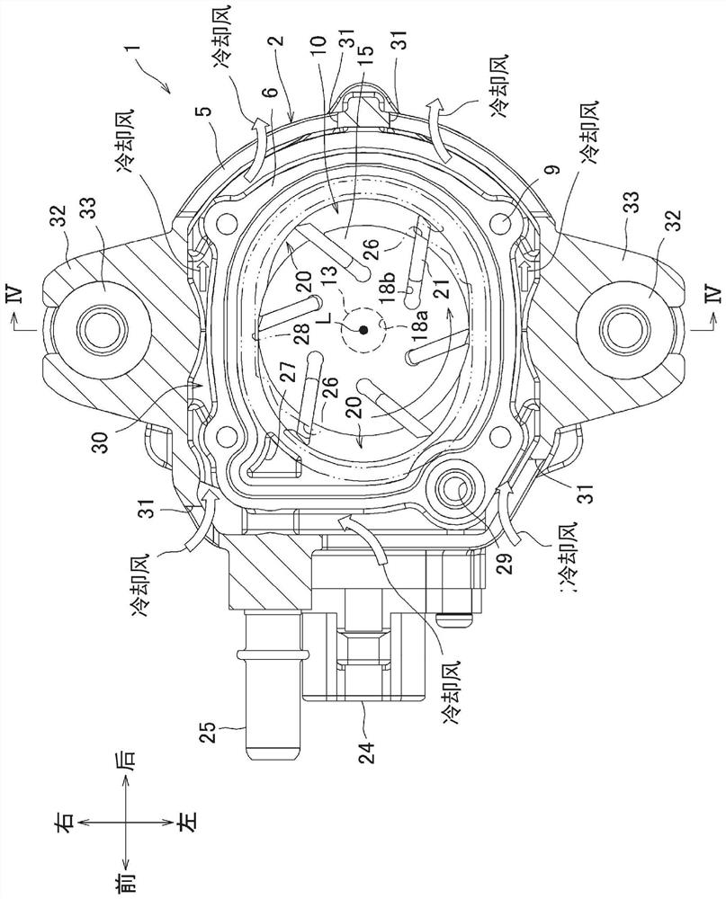
[0062] Figure 5 It is a schematic diagram which shows the planar shape of the accommodation space 10 in 1st Embodiment.

[0063] Basically, the housing space 10 of the vacuum pump 1 according to the present embodiment has the same structure as that of Patent Document 2, and is elliptical in plan view, and is represented by the following equation (1) on the X-axis and Y-axis planes, for example.

[0064] x 2 / A 2 +Y 2 / B 2 = 1...(1)

[0065] Here, A / B is the ratio of the major axis to the minor axis of the ellipse. The major axis of the storage space 10 corresponds to the "direction of parallel arrangement of the pump chambers" in the present invention, and the minor axis of the storage space 10 corresponds to the "direction perpendicular to the parallel arrangement direction" in the present invention.

[0066] The difference from the storage space of Patent Document 2 is as follows.

[0067] In the present embodiment, the internal dimension of the elliptical housing sp...

no. 2 approach

[0083] Figure 7 are the sum and Figure 6 The corresponding partial enlargement.

[0084] In the present embodiment, buffer surfaces C are formed at the boundaries between the elliptical surface B corresponding to the discharge side of each pump chamber 20 and each sealing surface A indicated by point b. The buffer surfaces C each have a cross-sectional arc shape with a radius Rc having a center p outside the housing space 10 , and the arc surface B and the sealing surface A are connected via the buffer surfaces C. By setting the position of the above-mentioned center p, the buffer surface C is curved in a direction opposite to the curved shape of the arcuate surface B and the sealing surface A. Specifically, the arcuate surface B and the sealing surface A are concave when viewed from the storage space 10 , whereas the buffer surface C is convex when viewed from the storage space 10 .

[0085] Therefore, when the vacuum pump 1 is in operation, the tips of the vanes 21 move...


PUM


Abstract

In the vane pump (1), a cylindrical rotor (18) is arranged in the housing space (10) provided in the pump casing (2), and the pump chamber (20) is divided on both sides of the rotor (18). ), and make the two sides of the outer peripheral surface of the rotor (18) perpendicular to the parallel arrangement direction of the pump chambers (20) respectively face the inner peripheral surface of the housing space (10) via a small gap, with the rotor (18) Rotate, while making the front end of the vane (21) that can be extended and retracted on the outer peripheral surface of the rotor (18) slide in contact with the inner peripheral surface of the housing space, the volume of each pump chamber (20) is changed, Thereby sucking and discharging the fluid, forming a pair of sealing surfaces (A) with a circular arc-shaped section corresponding to the outer peripheral surface of the rotor (18) on the inner peripheral surface of the housing space (10), so that the outer peripheral surface of the rotor (18) passes through The micro gaps are opposed to the regions of the sealing surfaces (A), and the sealing surfaces (A) are formed in regions offset to the discharge side of the pump chambers (20) in the direction in which the pump chambers (20) are arranged in parallel.

Description

technical field [0001] The invention relates to a vane pump. Background technique [0002] There are various forms in which the division state of the pump chamber differs in this type of vane pump. For example, in Patent Document 1 Figure 4 In the described vane pump, both sides of the cam ring are closed by plates to define a cylindrical housing space, and a cylindrical rotor is arranged at an eccentric position inside the housing space. Hereinafter, the above-mentioned form is referred to as an unbalanced type. In the above-mentioned unbalanced vane pump, a crescent-shaped single pump chamber is defined in the housing space, and as the rotor rotates, the vanes change the volume of the pump chamber to suck and discharge fluid. [0003] The capacity (fluid discharge rate) of the vane pump depends on the change in the volume of the pump chamber, but the increase in the size of the storage space for the purpose of increasing the capacity directly leads to the increase in th...

Claims


Application Information

Patent Timeline
Patent Type & Authority Patents(China)
IPC IPC(8): F04C18/344F04C25/02
CPCF04C25/02F04C18/3446F04C2250/30F04C29/0028
Inventor 小仓崇寛
Owner MIKUNI CORP
Learn More