MEMS microphone

A microphone and filter technology, which is applied in the direction of microphone structure association, microphone mouth/microphone accessories, microelectronic microstructure devices, etc., can solve problems such as MEMS microphone interference, large resistance, and MEMS microphone signal-to-noise ratio reduction, and achieve Effects of maintaining acoustic performance, preventing airflow impact, and reducing package size

Active Publication Date: 2019-12-13
WEIFANG GOERTEK MICROELECTRONICS CO LTD
View PDF9 Cites 1 Cited by
  • Summary
  • Abstract
  • Description
  • Claims
  • Application Information

AI Technical Summary

Problems solved by technology

Although the MEMS microphone is equipped with a protective part to prevent the impact of the external airflow on the MEMS acoustic-electric chip, but because the protective part is larger than the MEMS acoustic-electric chip, the package size of the MEMS microphone is limited, which is not conducive to miniaturization design.
In addition, the aperture of the communication hole of the protective member is smaller than the aperture of the acoustic hole, which has a large acoustic resistance, which leads to a serious decrease in the signal-to-noise ratio of the MEMS microphone and affects the acoustic performance of the MEMS microphone.
[0004] In addition, in the prior art MEMS microphones, there is a lack of anti-interference design for electromagnetic, radio frequency, light and suspended particles. Therefore, in the process of production and use, the above factors will cause interference to MEMS microphones, reducing the performance and stability

Method used


Image

  • MEMS microphone
  • MEMS microphone
  • MEMS microphone

Examples


Embodiment Construction

[0037] In order to make the objectives, technical solutions, and advantages of the present invention clearer, the embodiments of the present invention will be described in further detail below in conjunction with the accompanying drawings.

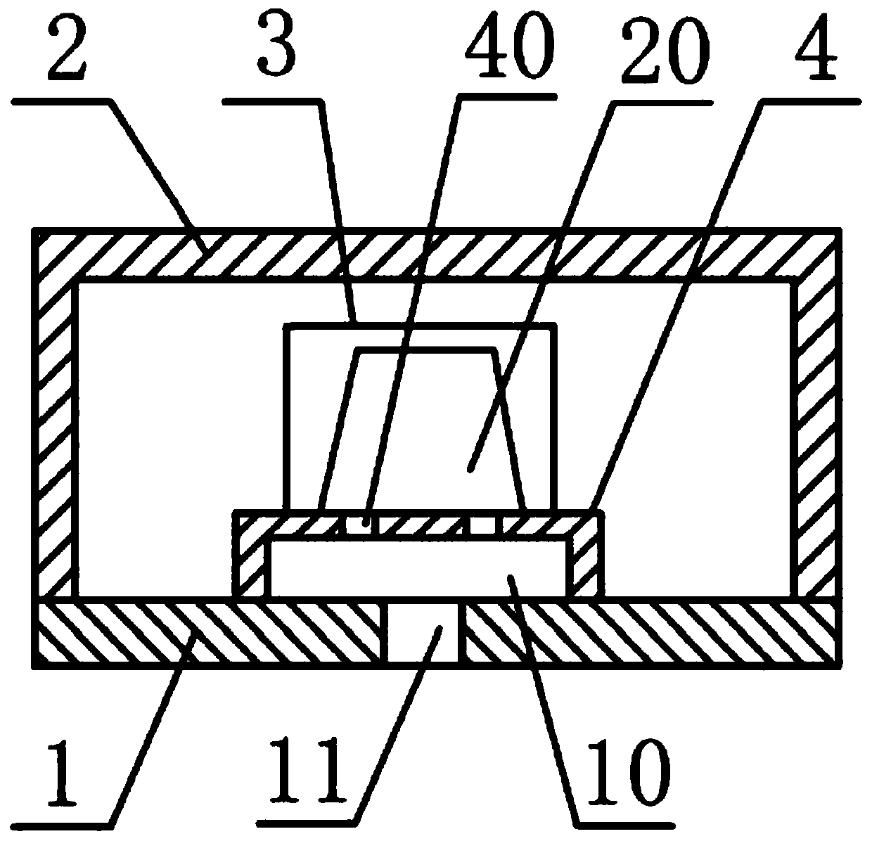
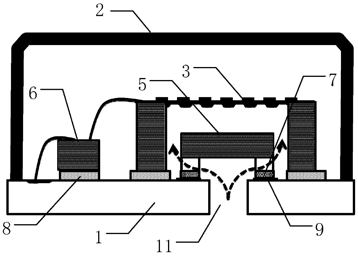
[0038] figure 2 It is a schematic diagram of a MEMS microphone structure provided by an embodiment of the present invention, such as figure 2 As shown, the MEMS microphone of the present invention includes a package structure surrounded by a PCB substrate 1 and a housing 2. The package structure is provided with a MEMS microphone 3, one end of the housing 2 is open, and the PCB substrate 1 basically seals the opening side of the housing 2. An acoustic hole 11 is provided on the PCB substrate 1 at a position corresponding to the MEMS acoustic-electric chip 3. The MEMS microphone also includes a filter 5 embedded in the back hole of the MEMS acoustic-electric chip 3. The filter 5 is connected to the PCB substrate 1. A horizontal hole is left b...


PUM


Abstract

A MEMS microphone, comprising a packaging structure that is enveloped by a PCB substrate (1) and a housing (2), wherein the packaging structure is provided with a MEMS acoustoelectric chip (3) therein, and the PCB substrate (1) is provided with a sound port (11) at a position that is corresponding to the MEMS acoustoelectric chip (3), wherein, the MEMS microphone further comprises a filter (5), wherein the filter (5) is embedded into a back cavity of the MEMS acoustoelectric chip (3), the filter (5) and the PCB substrate (1) have a lateral hole therebetween, and the lateral hole serves as a sound channel that is used by the MEMS acoustoelectric chip (3)to gather sound. The MEMS microphone can prevent gas shock, block the interfering to the MEMS microphone by kinetic particles, keep the acoustic performance of the MEMS microphone, and reduce the packaging size of the MEMS microphone.

Description

Technical field [0001] The invention relates to the field of acoustic-electric conversion, in particular to a MEMS microphone. Background technique [0002] With the advancement of society and the development of electronic technology, electronic products occupy an increasingly important position in people’s daily lives. For example, mobile phones have almost become necessities that people need to carry with them. In electronic products such as mobile phones, To realize functions such as calls, a microphone needs to be set to collect sound signals. In order to meet the performance requirements of electronic products and the development trend of miniaturization, MEMS (Micro-Electro-Mechanical System, Micro-Electro-Mechanical System) microphones are usually used. The MEMS microphone is a package structure composed of a shell and a printed circuit board (PCB). A MEMS acoustic-electric chip is provided on the surface of the circuit board inside the package structure, and a MEMS acous...

Claims


Application Information

Patent Timeline
Patent Type & Authority Applications(China)
IPC IPC(8): H04R19/04H04R1/08
CPCH04R19/005H04R19/04B81B7/0058B81B2201/0257H04R1/04H04R2201/003H04R2410/03
Inventor 邹泉波王喆晏嘉良
Owner WEIFANG GOERTEK MICROELECTRONICS CO LTD
Why Eureka
Try Eureka