Al technical title is built by PatSnap Al team. It summarizes the technical point description of the patent document.
A neurosurgery and supporting mechanism technology, applied in the field of medical devices, can solve the problems of no buffer mechanism, tearing of the knife edge, single function of the device, etc., and achieve the effects of avoiding excessive spacing, improving safety, and increasing applicability
Inactive Publication Date: 2019-12-17
王涛
View PDF1 Cites 8 Cited by
Summary
Abstract
Description
Claims
Application Information
AI Technical Summary
This helps you quickly interpret patents by identifying the three key elements:
Problems solved by technology
Method used
Benefits of technology
Problems solved by technology
[0003] In neurosurgery posterior cranial surgery, it is often necessary to use support devices and drainage devices in conjunction with surgery, but most of the existing devices have single functions and cannot combine the two, nor can they meet the different use requirements in posterior cranial surgery
[0004] In the patent application publication number CN 107823732 A, a neurosurgical posterior cranial distraction drainage device is disclosed, which includes a base, the base is a "Zhu" type plate, and the upper surfaces of the two ends of the base are relatively fixed with fixing plates , the shaft hole of the fixing plate is provided with a rotating shaft, the structure is simple, and the whole is fixed through the base, the skull at the operation position is stretched by the relative movement of the two pulling plates, and the intracranial bone is drained through the drainage tube and the negative pressure pump. The bleeding is drained into the negative pressure cylinder. The high position of the outlet of the drainage tube can effectively prevent the liquid in the negative pressure cylinder from flowing down. The deflection angle of the arm plate can be adjusted, and the position of the sliding seat on the arm plate can be adjusted. The height of the board and the drainage tube can also be adjusted accordingly, so that the drainage tube can safely enter the intracranial and reach the designated depth, thereby improving the success rate of the operation, reducing the risk of complications, and reducing the work difficulty of the medical staff; but its There are the following disadvantages: in this application, the arm plate has a circular arc structure, and the skull at the operation position is stretched by the movement of the arm plate, and the arm plate moves along the arm plate as a whole, so in the process of stretching the posterior skull , it is very easy to block the position of the incision, and it is easy to reduce the convenience for doctors to operate near the incision, and the puller does not have a buffer mechanism, which is very easy to cause the phenomenon of tearing the incision in the process of opening the posterior skull. At the same time, the drainage device is fixed On the stretching mechanism, the angle cannot be adjusted independently, and it cannot meet the fluid drainage under the complex structure inside the incision during the operation, and the overall applicability of the device is not good.
Method used
Image
Click on the blue label to locate the original text in one second.
Reading with bidirectional positioning of images and text.
Examples
Embodiment
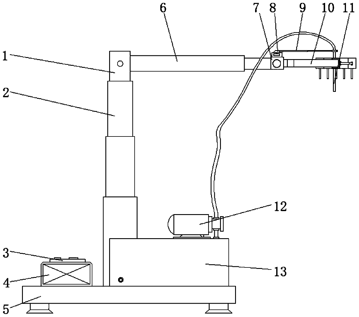
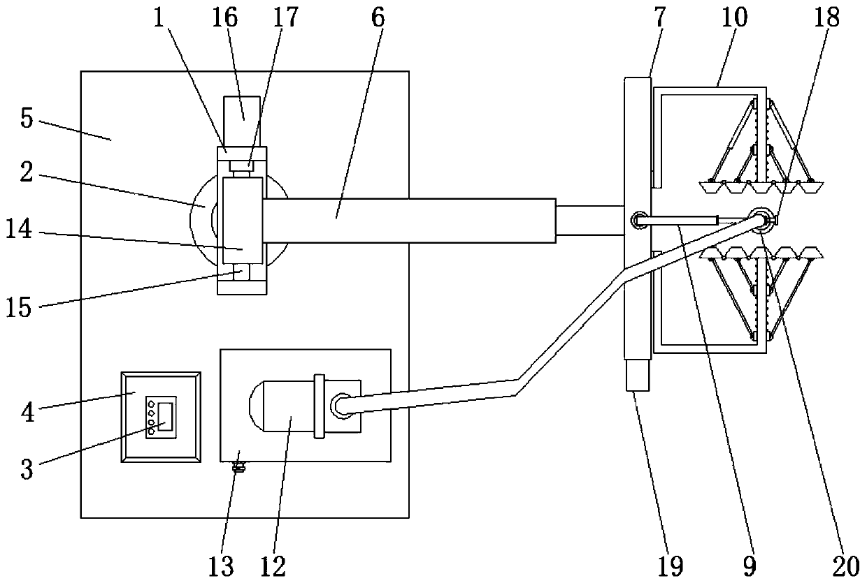
[0033] Such as Figure 1-5 The shown neurosurgery posterior cranial distraction drainage device includes a support mechanism, a distraction mechanism, and a drainage mechanism. The support mechanism includes a "U"-shaped frame 1, a hydraulic cylinder 2, a bottom plate 5, an electric push rod 6, and a sleeve 14 , a rotating shaft 15 and a drive motor 16, a hydraulic cylinder 2 is vertically fixed at the center of one end of the bottom plate 5, a "U" frame 1 is connected to the top of the hydraulic cylinder 2, and a drive motor 16 is fixed on the outside of one end of the "U" frame 1 The center of the "U" frame 1 is horizontally penetrated by a rotating shaft 15, and the center of the rotating shaft 15 is covered with a sleeve 14, and the output end of the drive motor 16 extends to the center of the "U" frame 1 and is fixed with a reducer 17 to reduce the speed The output end of device 17 is fixedly connected with one end of rotating shaft 15, and the outside of sleeve 14 is con...
PUM
Abstract
The invention discloses a neurosurgical posterior cranial distraction drainage device, which comprises a support mechanism, a distraction mechanism and a drainage mechanism. The support mechanism comprises a U-shaped frame, a hydraulic cylinder, a bottom plate, an electric push rod, a sleeve, a rotating shaft and a driving motor; the distraction mechanism comprises an adjusting part and a pair ofdistraction parts, and the adjusting part comprises a U-shaped seat, an L-shaped fixed rod, a stepping motor, a screw rod and a sliding block; and each distraction part comprises a hinge chain, a first sliding cylinder, a first spring rod, a second sliding cylinder, a second spring rod, a sliding rod and a reset spring; and the drainage mechanism comprises a telescopic rod, a drainage tube, an infusion pump, a catch box, a spring lock bolt and a fixing ring. By adopting the support mechanism, the distraction mechanism and the drainage mechanism, the surgical incision of a patient can be effectively opened and fixedly supported, the situation that the device tears the skin of the patient in the process of opening the surgical incision of the patient can be effectively avoided, and hydrops in the surgical incision of the patient can be effectively drained.
Description
technical field [0001] The invention relates to the technical field of medical devices, in particular to a neurosurgery posterior cranial distraction drainage device. Background technique [0002] Neurosurgery is a branch of surgery, which uses unique neurosurgery research methods to study the human nervous system, such as the brain, spinal cord and peripheral nervous system, as well as related diseases, based on surgery as the main treatment method. Injuries, inflammations, tumors, deformities, and certain genetic metabolic disorders or dysfunctional diseases of the skull, scalp, cerebrovascular meninges and other structures, so in neurosurgery, it is often necessary to perform intracranial surgery on the posterior cranium of the patient to treat the corresponding diseases. [0003] In neurosurgery posterior cranial surgery, it is often necessary to use support devices and drainage devices in conjunction with surgery, but most of the existing devices have single functions ...
Claims
Application Information
Patent Timeline
Application Date:The date an application was filed.
Publication Date:The date a patent or application was officially published.
First Publication Date:The earliest publication date of a patent with the same application number.
Issue Date:Publication date of the patent grant document.
PCT Entry Date:The Entry date of PCT National Phase.
Estimated Expiry Date:The statutory expiry date of a patent right according to the Patent Law, and it is the longest term of protection that the patent right can achieve without the termination of the patent right due to other reasons(Term extension factor has been taken into account ).
Invalid Date:Actual expiry date is based on effective date or publication date of legal transaction data of invalid patent.