
limb rehabilitation exoskeleton

A technology of exoskeleton and limbs, which is applied in the field of exoskeleton, can solve problems such as motion trajectory error, unfavorable recovery, and insufficient smoothness of motion trajectory, and achieve the effect of preventing trajectory deviation, increasing gravity sharing, and avoiding adverse effects

Active Publication Date: 2022-03-04
SHENZHEN CHWISHAY SMART TECH CO LTD
View PDF0 Cites 0 Cited by
  • Summary
  • Abstract
  • Description
  • Claims
  • Application Information

AI Technical Summary

Problems solved by technology

Because the active force of exercise cannot be provided during the patient's flaccid paralysis period, it is completely necessary to rely on the rehabilitation teacher to help the patient with training at this time, which greatly wastes manpower and time costs
Due to the limited amount of rehabilitation for each rehabilitation teacher per day, it cannot meet the rapidly growing needs of patients with brain tissue injuries and orthopedic injuries
Moreover, through artificial rehabilitation training in the acute phase, the rehabilitation mode cannot be well controlled, such as effective switching between passive, active, and impedance modes, or, in the existing rehabilitation training, some machines are used to assist guided rehabilitation, but now The trajectory of some auxiliary machinery is not smooth enough, there is a large error with the trajectory of the limbs, and the movement is not stable enough, resulting in unsatisfactory rehabilitation effects, and when the user uses it, due to the distribution of gravity, the exoskeleton may cause limb rehabilitation. Tilt, so the human body needs to support the tilted limb rehabilitation exoskeleton, which is not conducive to recovery

Method used


Image

  • limb rehabilitation exoskeleton
  • limb rehabilitation exoskeleton
  • limb rehabilitation exoskeleton

Examples


Embodiment Construction

[0033] The following will clearly and completely describe the technical solutions in the embodiments of the present invention with reference to the accompanying drawings in the embodiments of the present invention. Obviously, the described embodiments are only part of the embodiments of the present invention, not all of them. Based on the embodiments of the present invention, all other embodiments obtained by persons of ordinary skill in the art without creative efforts fall within the protection scope of the present invention.

[0034] It should be noted that all directional indications (such as up, down, left, right, front, back...) in the embodiments of the present invention are only used to explain the relationship between the components in a certain posture (as shown in the figure). Relative positional relationship, movement conditions, etc., if the specific posture changes, the directional indication will also change accordingly.

[0035] In the present invention, unless...


PUM


Abstract

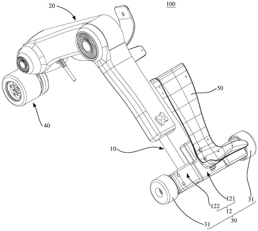
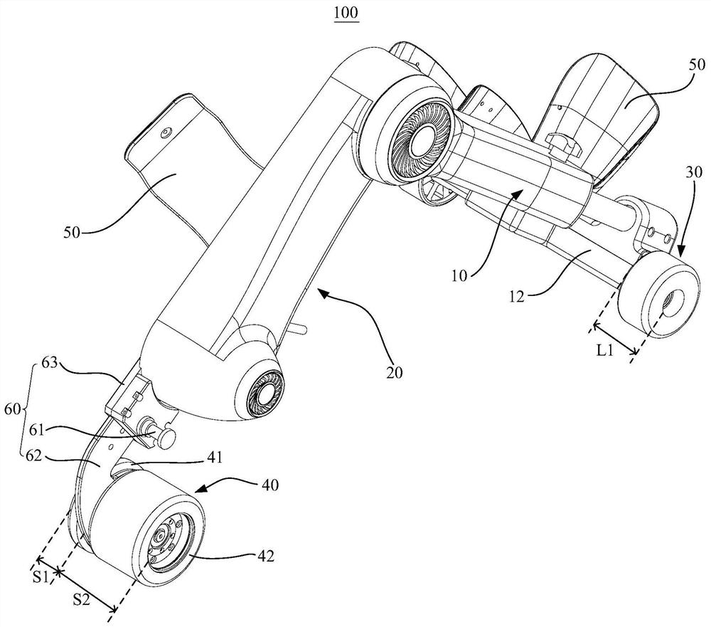
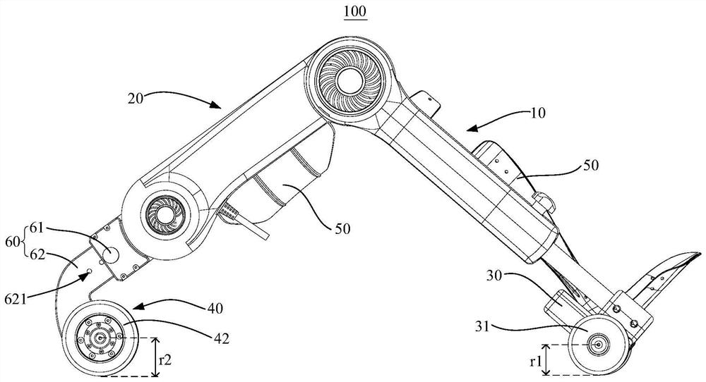
The invention discloses a limb rehabilitation exoskeleton. The limb rehabilitation exoskeleton includes: a first support rod; a second support rod, which is rotatably connected to the first support rod; a binding structure, which is used to fix part of the limbs on the second support rod. Two support rods, the binding structure is arranged on one side of the second support rod; the first guide wheel assembly, the first guide wheel assembly is arranged at the end of the first support rod away from the second support rod; and the second guide wheel assembly, the second guide wheel assembly The two guide wheel assemblies are located at the end of the second support bar away from the first support bar. The second guide wheel assembly includes an inner wheel and an outer wheel. The inner wheel and the outer wheel are respectively arranged on both sides of the second support bar. The binding structure is located on the same side as the second support rod. The technical solution of the present invention can play a guiding role when the exoskeleton is used to assist the rehabilitation of the human body, and fit the movement trajectory of the limbs to improve the rehabilitation effect, and avoid the adverse effects caused by the inclination of the limb rehabilitation exoskeleton when the user uses it.

Description

technical field [0001] The invention relates to the technical field of exoskeleton, in particular to a limb rehabilitation exoskeleton. Background technique [0002] In rehabilitation clinics, in the early and acute stages of rehabilitation for patients with stroke and cerebral palsy, it is often necessary to wake up and reshape the brain nervous system interrupted and disordered by brain tissue damage through joint activities. At the same time, joint activities can also be used to improve muscle strength and avoid Muscle atrophy, pressure sores on extremities, and other conditions. [0003] In the existing clinical rehabilitation departments, most of the rehabilitation teachers artificially help patients perform corresponding rehabilitation actions. Because the active force of movement cannot be provided during the patient's flaccid paralysis period, it is completely necessary to rely on the rehabilitation practitioner to help the patient with training at this time, which ...

Claims


Application Information

Patent Timeline
Patent Type & Authority Patents(China)
IPC IPC(8): A61H1/02B25J9/00
CPCA61H1/0237B25J9/0006B25J9/0009A61H2201/1642A61H2201/1659A61H2205/10A61H2201/50A61H2205/12A61H2201/1207
Inventor 谭高辉马舜朱俊杰
Owner SHENZHEN CHWISHAY SMART TECH CO LTD
Learn More