
Front-end sealing structure based on spindle

A sealing structure and spindle technology, which is applied to the sealing of engines, large fixed members, mechanical equipment, etc., can solve the problems of reducing the service life of the spindle, corrosion of the spindle, entering the spindle, etc., and achieve the effect of improving waterproof and dustproof effects

Pending Publication Date: 2019-12-17
深圳市爱贝科精密工业股份有限公司
View PDF0 Cites 3 Cited by
  • Summary
  • Abstract
  • Description
  • Claims
  • Application Information

AI Technical Summary

Problems solved by technology

[0004] The purpose of the present invention is to provide a front-end sealing structure based on the main shaft to solve the problem that water vapor and dust will enter the interior of the main shaft, which will cause corrosion to the main shaft and greatly reduce the service life of the main shaft.

Method used


Image

  • Front-end sealing structure based on spindle
  • Front-end sealing structure based on spindle
  • Front-end sealing structure based on spindle

Examples


Embodiment Construction

[0019] The following will clearly and completely describe the technical solutions in the embodiments of the present invention with reference to the accompanying drawings in the embodiments of the present invention. Obviously, the described embodiments are only some, not all, embodiments of the present invention. Based on the embodiments of the present invention, all other embodiments obtained by persons of ordinary skill in the art without making creative efforts belong to the protection scope of the present invention.

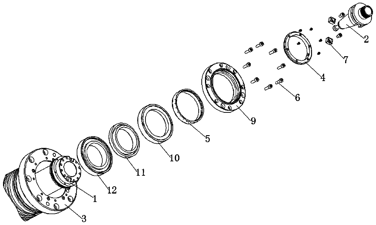
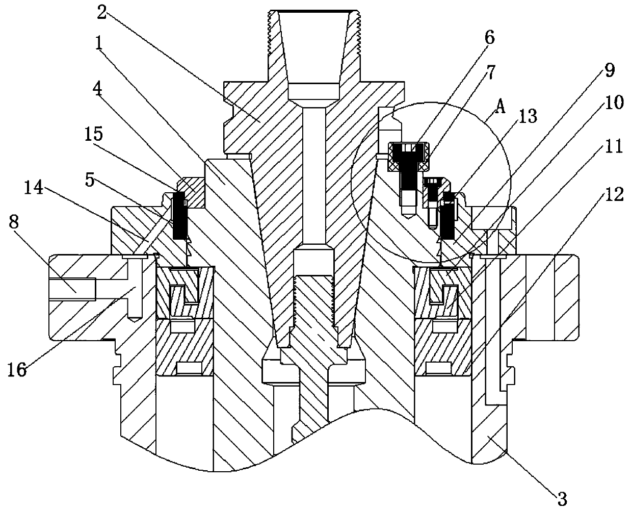
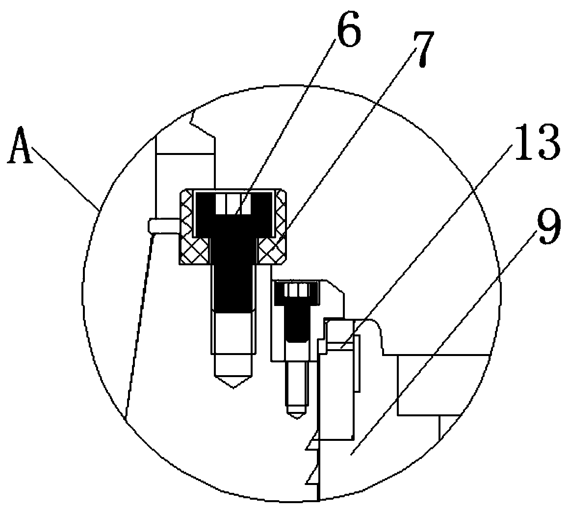
[0020] see Figure 1-3 , the present invention provides a technical solution: a front-end sealing structure based on an asynchronous electric spindle, including a rotor 1, a tool handle 2, a water jacket 3, a waterproof cover 4, a spacer ring assembly and a dust-proof ring assembly, and the tool handle 2 is docked on the On one side of the axis of the rotor 1, and the edge of the handle 2 and the rotor 1 is inlaid with a fixed block 7, and the fixed block 7 is...


PUM


Abstract

The invention discloses a front-end sealing structure based on a spindle. The structure comprises a rotor, a knife handle, a water jacket, a waterproof cover, a spacer ring assembly and a dustproof ring assembly; the knife handle is butted on one side of an axle center of the rotor; and a fixed block is inlaid at the edge of the knife handle and the rotor, and the fixed block is fixedly connectedwith the rotor through a screw, and the inner wall of the water jacket is connected with the outer wall of the rotor through a bearing connect in a sleeving manner. The front-end sealing structure based on the spindle is mainly composed of the water jacket, the dustproof ring assembly, an air ring and the waterproof cover, and can make air flow from an air sealing joint into an air sealing air path in the water jacket, and the air flow flows through the peripheral side of the air ring, and fills a gap, and then is discharged out of the spindle from the radial gap between the waterproof cover and the dustproof ring assembly, so that the dustproof effect of the spindle is greatly improved; and more preferably, when water splashes on the axial direction of the front-end of the spindle, the water hits the end face of the waterproof cover first so as to reduce the pressure of water vapor, and the air pressure of the radial gap can blow the splashed water to the periphery side of the gap, sothat the fact that the water vapor enters into the spindle is greatly avoided.

Description

technical field [0001] The invention relates to the technical field of CNC spindles, in particular to a spindle-based front end sealing structure. Background technique [0002] The CNC spindle is installed on the CNC milling machine to clamp the tool and drive the workpiece or the tool to rotate. However, the current spindle still has some shortcomings during use. [0003] At present, the front end of the spindle mechanism cannot achieve good sealing performance, so as to prevent water vapor and dust from entering the interior of the spindle when the spindle is cooling, causing corrosion to the spindle and greatly reducing the service life of the spindle. Contents of the invention [0004] The purpose of the present invention is to provide a front-end sealing structure based on the main shaft to solve the current problem that water vapor and dust will enter the interior of the main shaft, which will cause corrosion to the main shaft and greatly reduce the service life of t...

Claims


Application Information

Patent Timeline
IPC IPC(8): B23B19/02F16J15/40F16J15/16
CPCB23Q1/70F16J15/16F16J15/40
Inventor 李存杰
Owner 深圳市爱贝科精密工业股份有限公司
Learn More