End face grooving cutter body

A technology of grooving knife and end face, which is applied to the accessories of tool holders, tools for lathes, turning equipment, etc., and can solve the problems of designing relatively large adjustment holes, limited adjustment range, and unstable machining rigidity.

Active Publication Date: 2019-12-17
HENAN PINGGAO ELECTRIC +2
View PDF7 Cites 1 Cited by
  • Summary
  • Abstract
  • Description
  • Claims
  • Application Information

AI Technical Summary

Problems solved by technology

[0004] However, the adjustment hole in the above-mentioned patent is set on the sliding tool seat. When the diameter of the tool is large, because the volume of the sliding tool holder is limited, it is impossible to design a relatively large adjusting hole on the sliding tool seat, and the adjustment

Method used


Image

  • End face grooving cutter body
  • End face grooving cutter body
  • End face grooving cutter body

Examples


Embodiment Construction

[0025] Embodiments of the present invention will be further described below in conjunction with the accompanying drawings.

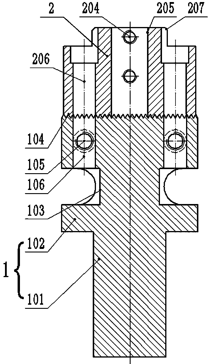
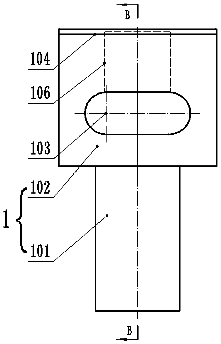
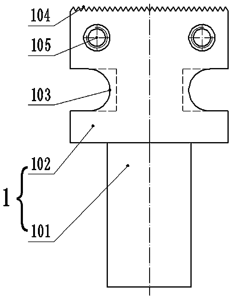
[0026] Specific embodiment 1 of the face grooving cutter body of the present invention, as Figure 1 to Figure 8 As shown, the end grooving cutter body includes a tool seat 1 for connecting with the machine tool spindle and a sliding tool holder 2 connected thereto through locking bolts, and a guide protrusion 104 is passed between the sliding tool holder 2 and the tool seat 1 It is guided and matched with the guide groove 201. The tool holder 1 is a stepped shaft, which includes an equipment connection part 101 for connecting with processing equipment such as machine tools and a tool holder connection part 102 for connecting with the sliding tool holder 2. The equipment connection part 101 is formed by the step shaft. A segment with a smaller shaft diameter is formed, and the toolholder connecting portion 102 is formed by a segment with a larger shaft ...


PUM


Abstract

The invention relates to an end face grooving cutter body. The end face grooving cutter body comprises a cutter base used for being connected with a main shaft of a machine tool. A sliding cutter holder is arranged on the cutter base. The sliding cutter holder and the cutter base are in guiding fit through guide protrusions and guide grooves. The sliding cutter holder is fixed to the cutter base through locking bolts. Holes, allowing the locking bolts to penetrate through, in the sliding cutter holder are circular holes. Long holes allowing the locking bolts to penetrate through are formed inthe cutter base. Long axes of the long holes are parallel to the guide movement direction of the sliding cutter holder. Slide grooves extending in the long-axis direction of the long holes are formedin the end, away from the sliding cutter holder, on the cutter base. Each slide groove is internally provided with a nut for connection of the corresponding locking bolt. The long holes for regulationare formed in the cutter base of the end face grooving cutter body, the holes in the sliding cutter holder are the circular holes, and therefore the size of connection holes in the cutter base is notlimited, the regulation range is wide, and the achievement of the grooving operation of large-diameter end face grooves is facilitated.

Description

technical field [0001] The invention relates to an end face grooving cutter body. Background technique [0002] On the end faces of high-voltage switch product components, it is often necessary to process sealing grooves, and the roughness and dimensional accuracy of the sealing grooves are required to be high. The quality of the end face grooves directly affects the performance of the product. The traditional way of processing end face grooves is to mill the end face of the product with milling cutters of various specifications or to use special grooving tools. However, in this processing method, the size of the tool cannot be adjusted, and a tool can only be processed with one size. The tool is not versatile, so the processing efficiency is low. [0003] The authorized announcement number is CN102825321B, and the Chinese patent authorized announcement date is 2014.09.17 discloses a face groove cutter with an adjustable structure. The sliding tool holder includes two oppo...

Claims


Application Information

Patent Timeline
IPC IPC(8): B23B27/00B23B29/00
CPCB23B27/00B23B29/00
Inventor 刘振才李宏楼曹国彬樊金民陈俊磊李二生
Owner HENAN PINGGAO ELECTRIC
Why Eureka
Try Eureka