High-rigidity double-spindle vertical machining center

A vertical machining center and dual-spindle technology, which is applied in metal processing, metal processing equipment, metal processing machinery parts, etc., can solve the problems of increasing labor intensity of workers, weak rigidity, and large footprint of machining centers, and achieve reduction Spindle overhang, reduce Z-direction overhang, reduce the effect of Z-direction travel

Pending Publication Date: 2021-12-24
林志贺
View PDF0 Cites 0 Cited by
  • Summary
  • Abstract
  • Description
  • Claims
  • Application Information

AI Technical Summary

Problems solved by technology

Conventional processing centers occupy a large area, and workers have to walk more distances when operating multiple machines, which increases the labor intensity of workers and affects work efficiency; in addition, with the shrinking of land resources, the cost of processing sites is getting higher and higher, so It is hoped that the equipment can be more compact and miniaturized, so as to increase the volume ratio of the workshop and reduce management costs
In recent years, there have been many vertical machining centers with double spindles on the market. They all adopt the structure of parallel double spindles of traditional vertical machining centers. The structure is as follows: figure 1 As shown, the overhang distance from the main shaft core (101) to the guide rail (102) is very long, resulting in weak rigidity, and this shortcoming is more obvious in the case of dual spindles; resulting in shortened machining efficiency, precision and tool life , not conducive to popularization

Method used


Image

  • High-rigidity double-spindle vertical machining center
  • High-rigidity double-spindle vertical machining center
  • High-rigidity double-spindle vertical machining center

Examples


Embodiment Construction

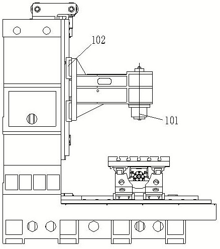
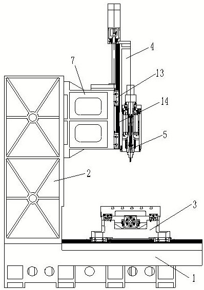
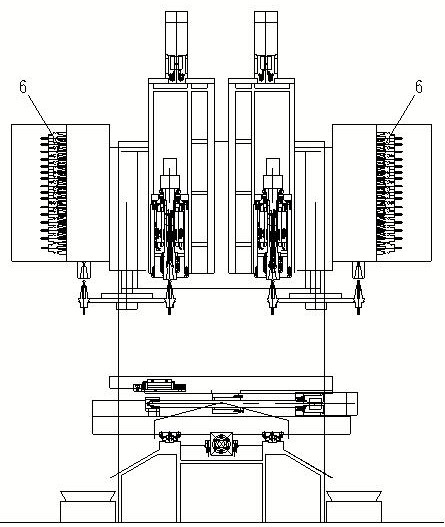
[0017] refer to figure 2 , 3 In the first embodiment shown, in this embodiment, the spindle unit adopts a short-nose electric spindle unit (5), and the tool magazine adopts a rotating arm manipulator type disc tool magazine (6). refer to Figure 4 There are two T-shaped slots (11) parallel to the axis of the main shaft and a set of matrix positioning pin holes (8) on the mounting surface of the column (2) and the upper and lower adjustment seats (7); the upper and lower adjustment seats (7) The matrix positioning pin holes (8) on the column (2) corresponding to the mounting surface of the column (2) are also processed with a set of matrix positioning pin holes 2 (9); the installation of the upper and lower adjustment seats (7) and the column (2) The surface corresponds to the T-shaped groove (11) on the column (2) and is also correspondingly processed with screw mounting holes (12).

[0018] refer to figure 2 , 3 . In the first embodiment shown in 4, the column (2) is f...


PUM


Abstract

The invention relates to a high-rigidity double-spindle vertical machining center. The high-rigidity double-spindle vertical machining center mainly comprises a base, a stand column, a cross numerical control sliding table, Z-direction numerical control sliding tables, main shaft units and tool magazines, wherein an up-and-down adjusting seat is arranged between each Z-direction numerical control sliding table and the stand column; two Z-direction numerical control sliding tables, two main shaft units and two tool magazines are arranged left and right; and the tool magazines are fixedly mounted on the up-down adjusting seats and are arranged on the side surfaces of the main shaft units. The rigidity is high, synchronous tool changing of two main shafts can be carried out simultaneously, and length compensation of tools on the main shafts can be independently carried out; and the high-rigidity double-spindle vertical machining center is simple in structure and convenient to maintain and is ideal drilling and milling comprehensive machining equipment.

Description

technical field [0001] The invention relates to a vertical machining center, in particular to a double-spindle vertical machining center. Background technique [0002] With the revitalization and development of the national equipment manufacturing industry, CNC machine tools, as the mainstream product of the machine tool industry, have become the key equipment to realize the modernization of the equipment manufacturing industry. Conventional processing centers occupy a large area, and workers have to walk more distances when operating multiple machines, which increases the labor intensity of workers and affects work efficiency; in addition, with the shrinking of land resources, the cost of processing sites is getting higher and higher, so It is hoped that the equipment can be more compact and miniaturized, so as to increase the volume ratio of the workshop and reduce management costs. In recent years, there have been many vertical machining centers with double spindles on t...

Claims


Application Information

Patent Timeline
Patent Type & Authority Applications(China)
IPC IPC(8): B23Q41/04B23Q3/155
CPCB23Q41/04B23Q3/15526B23Q3/1554
Inventor 林志贺
Owner 林志贺
Why Eureka
Try Eureka