Hybrid vehicle

A hybrid vehicle, power technology, applied in the direction of hybrid vehicles, motor vehicles, electric vehicles, etc., to achieve the effect of reducing the length

Inactive Publication Date: 2010-11-24
HONDA MOTOR CO LTD
View PDF4 Cites 5 Cited by
  • Summary
  • Abstract
  • Description
  • Claims
  • Application Information

AI Technical Summary

Problems solved by technology

[0005] However, in this power unit, since the electric motor is located rearward and downward compared to the crankshaft of the internal combustion engine and is located further outside in the width direction than the driven pulley constituting the continuously variable transmission, the electric motor is arranged on the side of the rear wheel and Overhangs a lot in the width direction

Method used


Image

  • Hybrid vehicle
  • Hybrid vehicle
  • Hybrid vehicle

Examples


Embodiment Construction

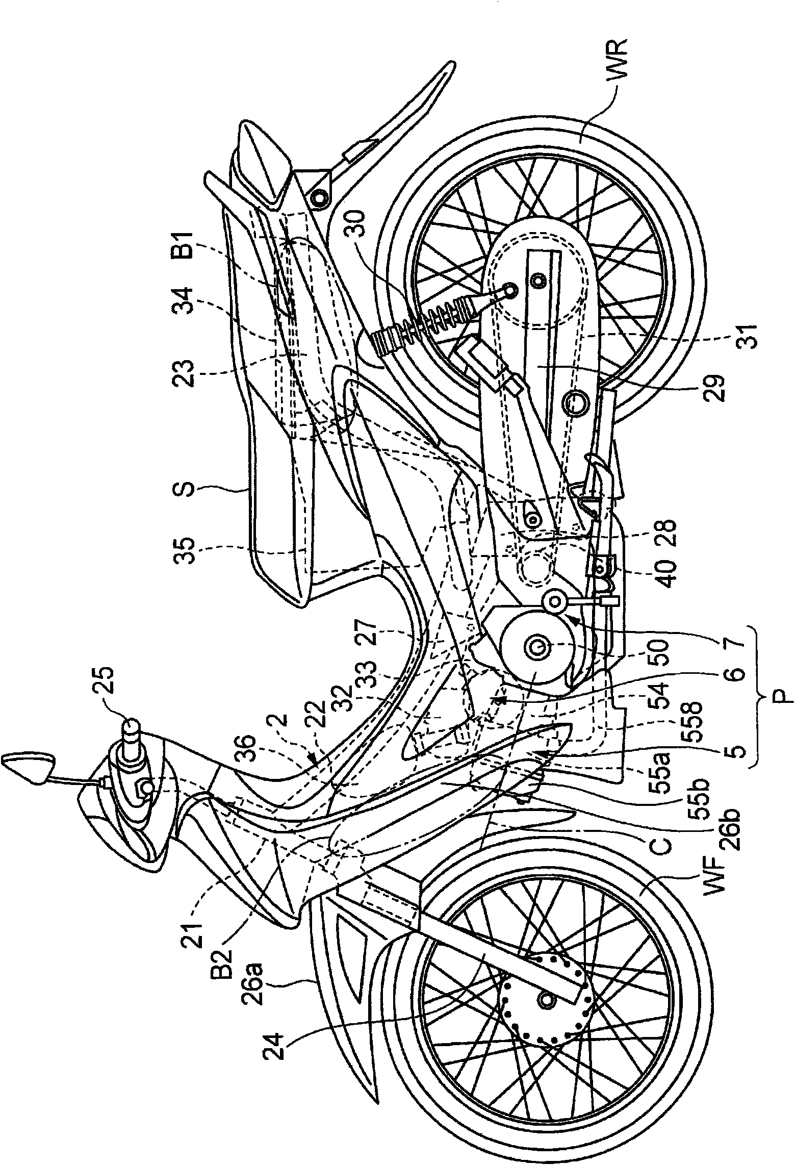
[0093] Hereinafter, an embodiment of a hybrid vehicle according to the present invention will be described with reference to the drawings. figure 1 It is a side view of an embodiment of the hybrid vehicle of the present invention.

[0094] The hybrid vehicle of the present invention is a two-wheeled motor vehicle. The frame 2 of this two-wheeled motor vehicle 1 includes a head pipe 21 that supports a front fork 24 in a steerable direction, a main frame 22 extending rearward and downward from the head pipe 21, and a rear portion connected to the main frame 22. And a pair of left and right rear vehicle frames 23 extending rearward and upward. The front wheel WF is pivotally supported on the lower end of the front fork 24 , a rod-shaped steering handle 25 is connected to the upper portion of the front fork 24 , and a front fender 26 a covering the front wheel WF is supported above the front fork 24 . In addition, this motorcycle 1 is provided with a leg protection panel 26b ext...


PUM


Abstract

To provide a hybrid vehicle in which an electric motor is disposed in the vicinity of a center of a vehicle body to reduce lateral expansion. The hybrid vehicle includes: an engine (5); a motor (6); and a power transmission mechanism (7) for transmitting powers of the engine (5) and the motor (6) to a rear wheel WR. The engine (5) is suspended on the vehicle body in a non-shaky manner, with a cylinder (54) extending in a substantially horizontal direction and a crankshaft (50) provided to be oriented in a vehicle width direction. Also, the motor (6) is located in front of and above the crankshaft (50) of the engine (5).

Description

technical field [0001] The present invention relates to a hybrid vehicle having two drive sources of an internal combustion engine and an electric motor. Background technique [0002] As a power unit for a hybrid vehicle mounted on a two-wheeled vehicle, for example, a power unit for a hybrid vehicle of Patent Document 1 is known (for example, Patent Document 1). [0003] In the hybrid vehicle power unit of Patent Document 1, the power from the internal combustion engine is transmitted to the rear wheels via the belt-type continuously variable transmission and the gear-type transmission constituting the power transmission mechanism, and the power from the electric motor is transmitted to the rear wheels via the gear-type transmission. wheel. This electric motor is arranged coaxially with the driven pulley constituting the continuously variable transmission, and is located on the side of the rear wheel. [0004] Patent Document 1: Japanese Patent Laid-Open No. 2006-044495 ...

Claims


Application Information

Patent Timeline
Patent Type & Authority Applications(China)
IPC IPC(8): B60K6/22B60K6/24B60K6/26B60K6/36B60K6/38B62M23/02B60L50/16
CPCB60L2200/12B62M23/02B60L11/14B60L7/18B60Y2200/12B60K6/48Y02T10/7077B62K11/04B60K6/40Y02T10/6221B60W2300/36B60L50/16Y02T10/62Y02T10/7072Y02T10/70
Inventor 野村明史中井一之大森谦一塚田善昭堤崎高司我妻伸一
Owner HONDA MOTOR CO LTD
Why Eureka
Try Eureka