Power converter

a power converter and converter technology, applied in the direction of dc-ac conversion without reversal, electrical apparatus construction details, and semiconductor/solid-state device details, can solve the problems of low accuracy of current sensors and the increase of power converter volume, and achieve the effect of excellent vibration resistance and minimizing the influence of nois

Active Publication Date: 2018-03-22
HONDA MOTOR CO LTD
View PDF6 Cites 5 Cited by
  • Summary
  • Abstract
  • Description
  • Claims
  • Application Information

AI Technical Summary

Benefits of technology

[0022]According to the present invention, it is possible to realize a power converter in a small size having excellent vibration resistance in which an overhang of power modules protruding from a portion sandwiched by a holding structure can be reduced and by which the influence of noise can be minimized.

Problems solved by technology

Thus, a volume of the power converter increases, and the accuracy of the current sensor is low because the longer wiring picks up noise.

Method used


Image

  • Power converter
  • Power converter
  • Power converter

Examples


Embodiment Construction

[0035]The present invention will be introduced below by describing a power converter as an embodiment of the present invention with reference to the drawings. First, the power converter of the embodiment of the present invention will be described in detail with reference to FIGS. 1 to 3.

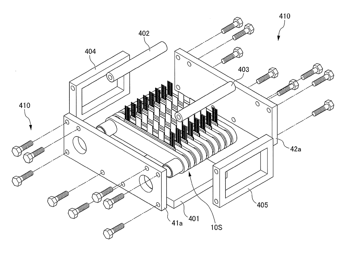
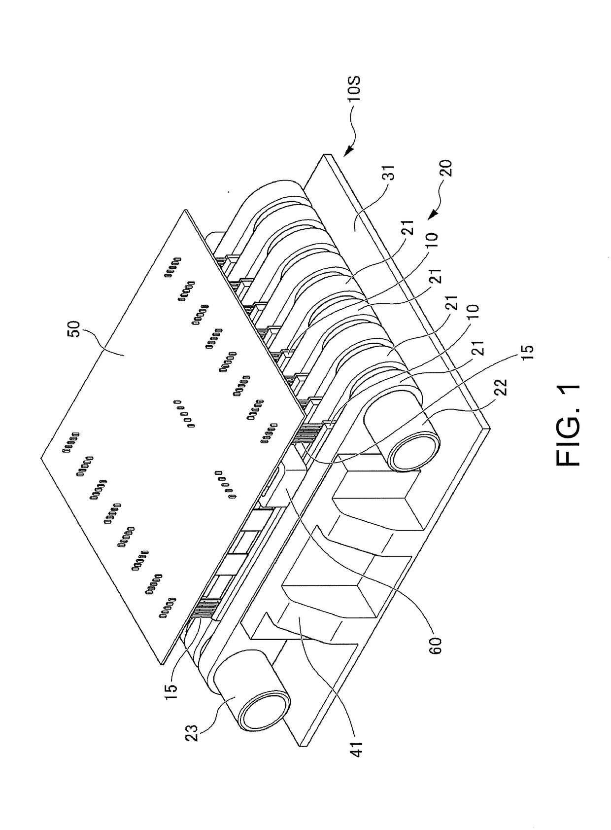
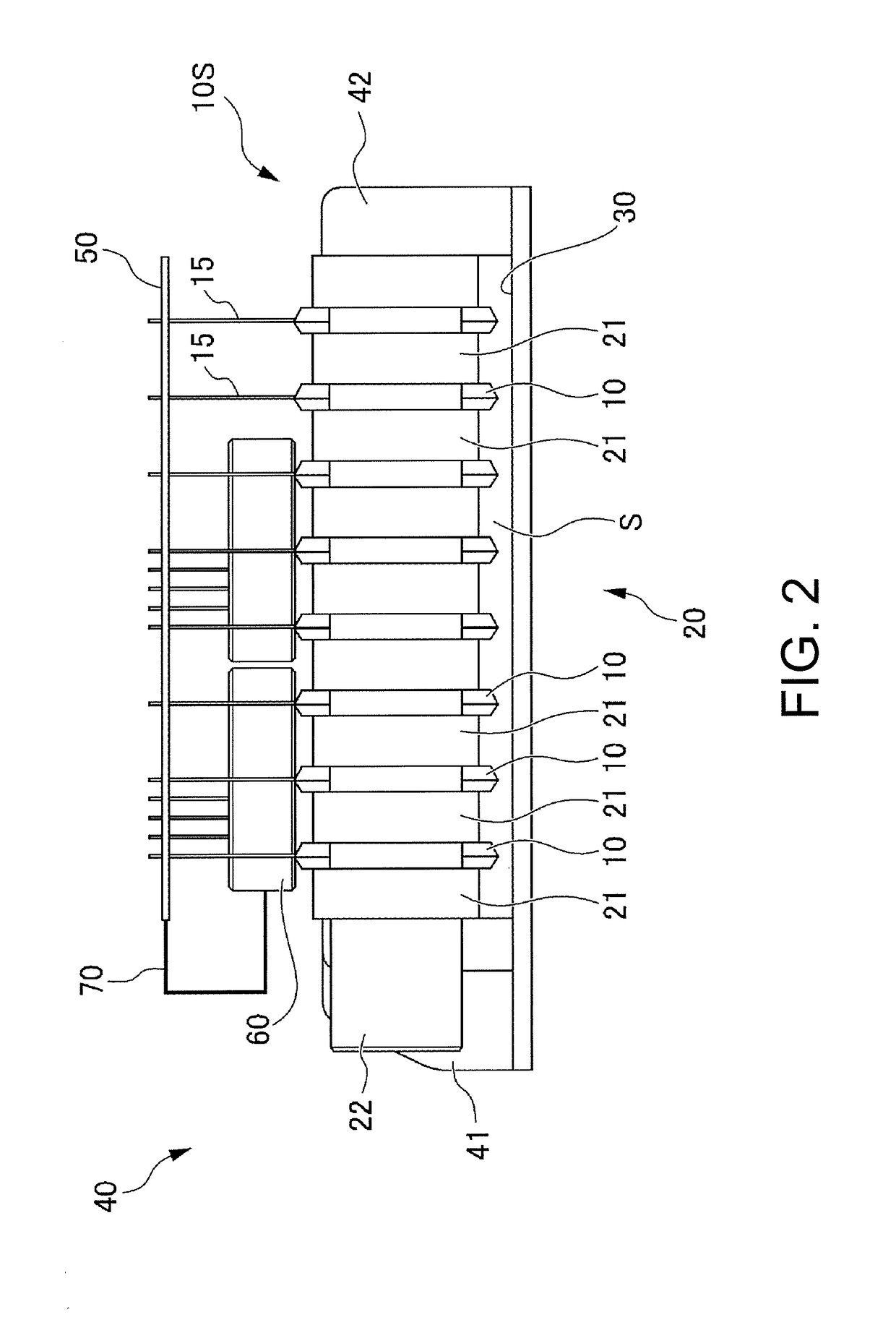
[0036]FIGS. 1 to 3 are diagrams showing the power converter of the embodiment of the present invention, FIG. 1 is a perspective view of the power converter, FIG. 2 is a side view of the power converter, and FIG. 3 is a perspective view showing a disposition of a conductor part of the power converter. The same reference numerals are given to corresponding portions in FIG. 1 to FIG. 3. The power converter 1 as an embodiment of the present invention includes semiconductor modules 10, a cooler 20, and a cover 30. That is, a plurality of power modules 10 which are planar semiconductor modules are disposed to be laminated such that each of the power modules 10 are interposed between a plurality of planar r...


PUM


Abstract

A power converter (1) includes: planar semiconductor modules (10) each having a resin sealing part (16) in which a semiconductor element (11), conductive members (12, 13, and 14), and a signal terminal (15) are sealed with a resin; a cooler (20) that holds the plurality of semiconductor modules (10) in a laminated manner; and a cover (30) that covers the semiconductor modules and the cooler, wherein at least a part of the resin sealing part (16) and the cooler (20) are supported by support media (41 and 42) that extend from the cover (30) so that facing parts of the resin sealing part and the cooler with respect to the cover (30) is positioned in proximity to the cover, and the conductive members and the signal terminal protrude from the resin sealing part in a direction away from the cover.

Description

CROSS-REFERENCE TO RELATED APPLICATION[0001]This application claims the priority benefit of Japan application serial no. 2016-184418, filed on Sep. 21, 2016. The entirety of the above-mentioned patent application is hereby incorporated by reference herein and made a part of this specification.BACKGROUND OF THE INVENTIONField of the Invention[0002]The present invention relates to a power converter.Description of Related Art[0003]In the past, a power converter 1000 was disclosed to which a power module 100 was applied. Signal pins 150 extend from one side of the power module and are connected to a control board, and bus bar 200 extend from the other side of the power module, as shown in a perspective view of a semiconductor module in FIG. 10. Power modules and a cooler were interposed together in a holding structure 700 of the power converter of the related art shown in FIGS. 11 and 12 (e.g., refer to Patent Literature 1).PRIOR ART DOCUMENTPatent Document[0004][Patent Document 1] Japa...

Claims


Application Information

Patent Timeline
Patent Type & Authority Applications(United States)
IPC IPC(8): H02M7/00H02M7/48H05K7/14H01L21/48H05K7/20H02P27/06H05K7/02
CPCH02M7/003H02M7/48H05K7/1432H01L21/4878H05K7/20927H02P27/06H05K7/023H05K7/2089H02M7/537H01L23/46H02M1/00H05K7/14329H01L23/473
Inventor HAGIMOTO, TAKAHIROUNEME, TAKAHIROYAMADA, YUKO
Owner HONDA MOTOR CO LTD
Why Eureka
Try Eureka