Heatsink and semiconductor device with heatsink

a heatsink and semiconductor technology, applied in semiconductor lasers, electrical apparatus construction details, light and heating apparatus, etc., can solve the problem of relatively high water leakage probability, achieve high output light source, reduce the number of parts, and enhance watertight performance

Active Publication Date: 2009-02-12
PANASONIC INDAL DEVICES SUNX
View PDF26 Cites 5 Cited by
  • Summary
  • Abstract
  • Description
  • Claims
  • Application Information

AI Technical Summary

Benefits of technology

[0030]In the second aspect of the invention, since the sheet-shape sealing member is interposed between the heatsink body and the header, only one sheet of the sealing member is used for the first and second orifices even in a case that the sealing member is provided individually for each heatsink body. It is possible to maintain the watertight couplings with a relatively small number of the seaming member, that is, only the sealing members of the same number as the heatsink bodies. Further, it is also possible to provide one sheet of the sealing member for plural heatsink bodies. Accordingly, it is possible to provide with a smaller number of the parts. In addition, in a case that the sealing member is formed with an insulating material, the heatsink body can double as the electrode, and even in a case that the header is made of a metal, the sealing member can double as the insulating material that is disposed between the heatsink body and the header. As a result, the number of the parts can be reduced.
[0031]In the third aspect of the invention, the insertion tubes projecting on the heatsink body are inserted in the receiving tubes provided in the header, and a watertight sealing is performed between the insertion tubes and the receiving tubes by the sealing members provided inside the receiving tubes. Accordingly, watertight performance can be enhanced by making a sealing distance long at the sealing locations. Further, by inserting the insertion tubes in the receiving tubes in the header, the heatsink body can be positioned and tentatively fixed on the header. Therefore, the mounting process of the heatsink body to the header can be performed easily.
[0032]In the fourth aspect of the invention, recesses are formed at least either around the circulation orifices in the contact surface of the heatsink body or around the supply port and the discharge port in the mount surface of the header, annular sealing members that exhibit rubber elasticity are disposed in the recesses, and the heatsink body is joined to the header such that the sealing members are compressed between the heatsink body and the header. Therefore, the sealing members are brought into almost linear contacts with the heatsink body and the header. It is possible to closely contact the sealing members with the heatsink body and the header regardless of flatness of the heatsink body and the header. As a result, no gap is formed between the heatsink body and the sealing members as well as between the header and the sealing members, and the leakage of the cooling fluid is hardly occurred even if high pressured is exerted.
[0033]In the fifth aspect of the invention, by cooling the light emitting diode, it is possible to obtain a high output light source using a light emitting diode. In general, the light emission efficiency is deteriorated when the temperature of the light emitting diode is elevated. In the invention, by forcibly cooling the light emitting diode by circulating the cooling fluid, it is possible to suppress the temperature rise even when large current is input, and it is possible to illuminate the light source with high output maintaining the light emission efficiency.
[0034]In the sixth aspect of the invention, since the header is formed with the insulating synthetic resin material, it is possible to mount the heatsink body on the header so as to directly contact with each other even in a case that the heatsink body doubles as an electrode. Therefore, it is not necessary to interpose an insulating material between the heatsink body and the header as it is in a case that the header is made of a metal. Thus, the number of parts can be reduced.
[0035]In the seventh aspect of the invention, the heatsink body is provided by interposing the insulating material layer between two metal plates of the base substrate and the cover substrate. Two electrodes of the semiconductor device mounted on the cover substrate are connected with the base substrate and the cover substrate, respectively. Therefore, it is possible to increase electrode areas to increase large current capacity as compared with a case in which terminal pins and lead wires are used for electric connections. In addition, since the heatsink body doubles as electric connection sections, it is possible to reduce projecting parts from the heatsink body as compared with a case in which electric connection sections such as terminal pins and lead wires are separately provided. Therefore, the heatsink body can be easily attached to the header or other members and can be housed compactly.

Problems solved by technology

However, there has been a problem that possibility of occurrence of leakage of water becomes relatively high because plural locations have to be coupled in a watertight manner.

Method used


Image

  • Heatsink and semiconductor device with heatsink
  • Heatsink and semiconductor device with heatsink
  • Heatsink and semiconductor device with heatsink

Examples


first embodiment

[0049]A heatsink to be described below is explained by taking, as an example, a case where the heatsink includes a UV-ray light emitting diode as a heating element. Incidentally, in the invention, not only the UV-ray light emitting diode emitting light of ultra-violet ray wavelength range, but also a light emitting diode other than the UV-ray light emitting diode, such as one emitting light of visible wavelength range, can be adapted as the heating element. Further, other power semiconductor elements can be also adapted as the heating element.

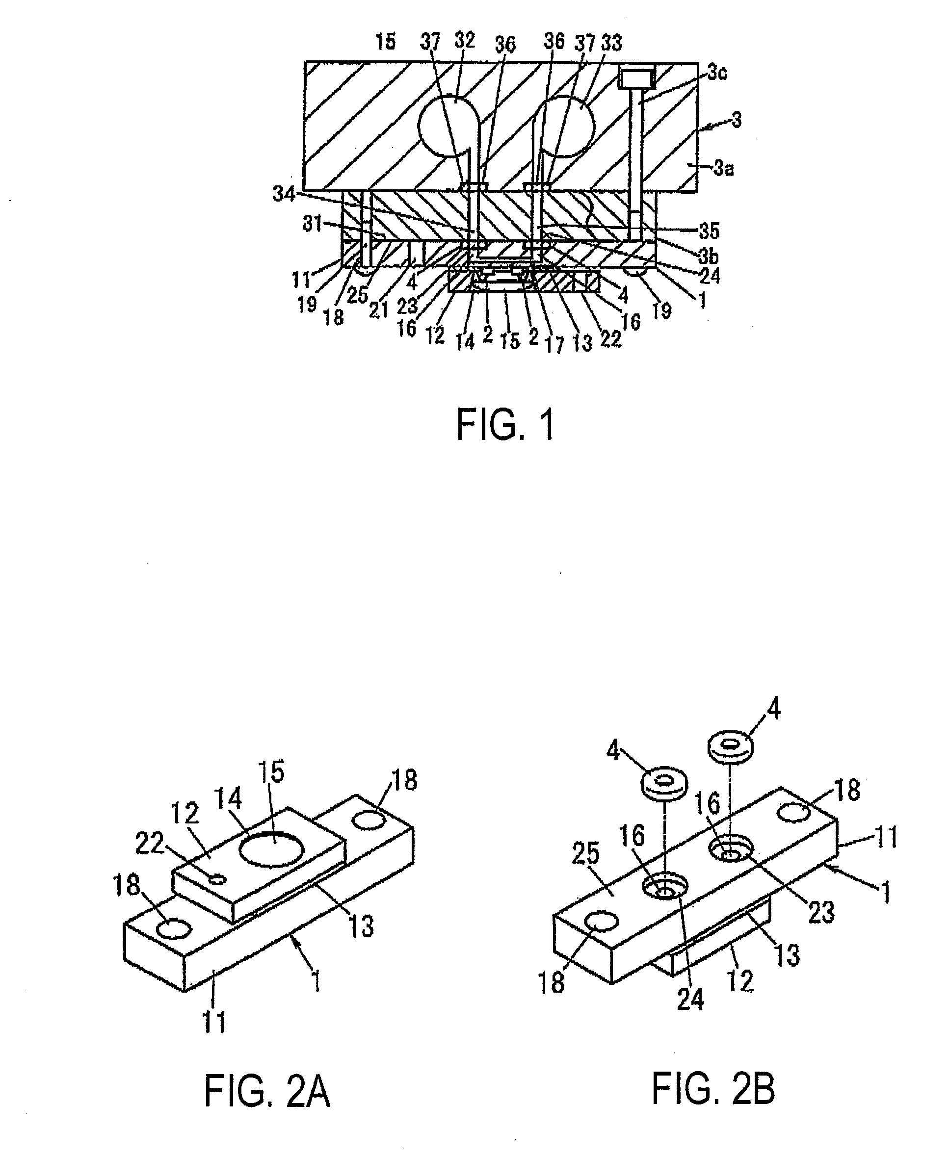
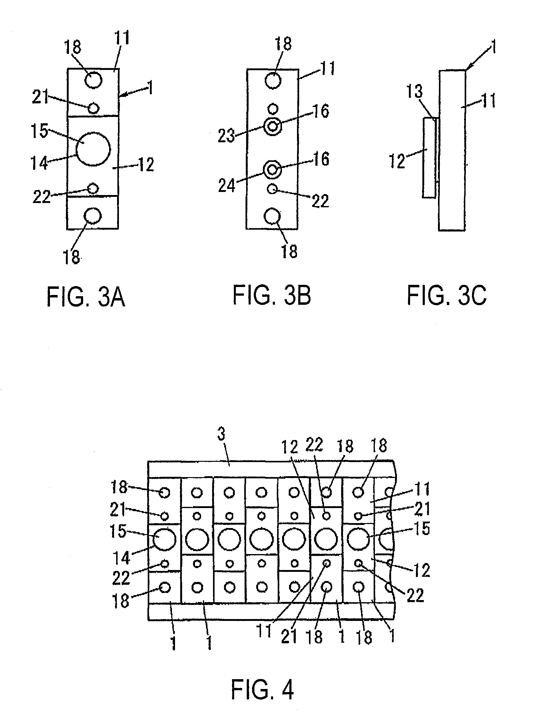
[0050]As shown in FIGS. 1 through 3, a heatsink body 1 is constructed as a layered product generated by stacking a base substrate 11 made of a metal plate on which a UV-ray light emitting diode 2 corresponding to a bear chip is mounted, a cover substrate 12 made of a metal plate surrounding an area of the base substrate 11 where the UV-ray light emitting diode 2 is mounted, and an insulating material layer 13 that is interposed between the base...

second embodiment

[0065]In the first embodiment, the structure is provided such that the heatsink body 1 and the header 3 are coupled in the watertight manner by use of the annular sealing member 4. On the other hand, in the present embodiment, the structure is provided such that a sheet-shape sealing member 5 is employed instead of the annular sealing member 4. Further, in the first embodiment, the recesses 23 and 24 are provided for housing the sealing members 4 in the heatsink body 1. On the other hand, in the present embodiment, the recesses 23 and 24 are unnecessary.

[0066]The sealing member 5 has such dimensions as to be the same as the entire area of the surface of the base substrate 11 constituting the heatsink body 1 that opposes to the header 3. The sealing member 5 is made of a material that exhibits a rubber elasticity similarly to the sealing member 4. In the sealing member 5, a supply hole 41 and a discharge hole 42 for communicating the supply port 34 and the discharge port 35 to the re...

third embodiment

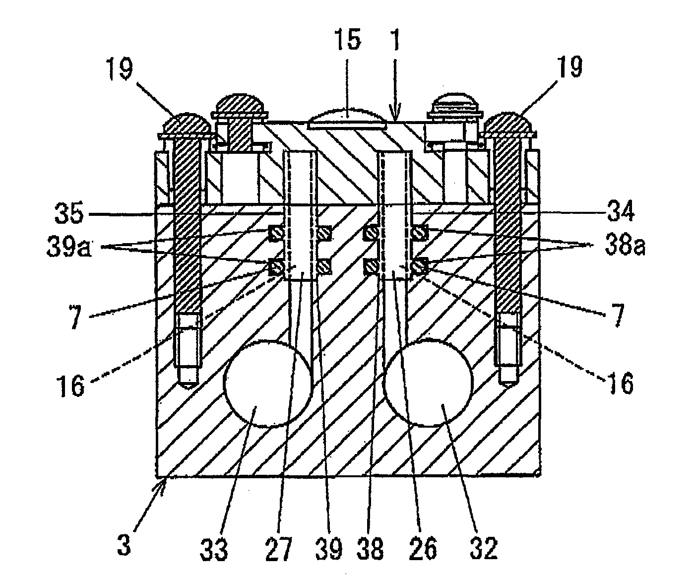
[0070]In the present embodiment, as shown in FIGS. 9 and 10, a pair of insertion tubes 26 and 27 are provided so as to project from the base substrate 11 of the heat sink body 1, and the heatsink body 1 is mounted on the header 3 in a state that the insertion tubes 26 and 27 are inserted in the header 3. The circulation orifices 16 are formed through the insertion tubes 26 and 27.

[0071]In the header 3, as shown in FIG. 10, a first receiving tube 38 which communicates with the supply path 32 at one end and is opened to the supply port 34 at the other end and a second receiving tube 39 which communicates with the discharge path 33 at one end and is opened to the discharge port 35 at the other end are formed. Inside of each receiving tubes 38 and 39, a pair of retaining grooves 38a and 39a are formed to retain sealing members 7, so that the sealing members 7 are retained at predetermined positions in the receiving tubes 38 and 39.

[0072]The receiving tubes 38 and 39 have a diameter and ...


PUM


Abstract

A heatsink carries a UV-ray light emitting diode. Flow passages for causing circulation of a fluid that cools the UV-ray light emitting diode are opened in the heatsink. Supply ports and discharge ports are opened in a mount surface of a header where supply and discharge of the fluid for cooling purpose to and from the heatsink are performed. A pair of circulation orifices corresponding to the supply port and the discharge port are opened in the contact surface that contacts the mount surface in the heatsink. Recesses are formed around the respective circulation orifices, and an annular sealing member that exhibits rubber elasticity and that is compressed between the heatsink and the header is disposed in each of the recesses.

Description

BACKGROUND OF THE INVENTION[0001]1. Field of the Invention[0002]The present invention relates to a heatsink that cools a heating element by use of a fluid for cooling purpose as well as to a semiconductor device having a heatsink for which a heating element is a semiconductor element.[0003]2. Related Art[0004]A radiator and a heatsink have hitherto been used for cooling a heating element, such as a semiconductor element. In particular, since calorific power of a power semiconductor is large, a configuration for circulating a fluid for cooling purpose within a heat sink has been put forward (see, for instance, JP-A-2006-19676).[0005]JP-A-2006-19676 describes a unit module light source in which a heatsink provided with a light emitting diode serving as a heating element is fastened to a fixing jig by screws. There is also a description about use of, between the heatsink and the fixing jig, a resin or metal member for coupling a supply port for introducing a fluid for cooling purpose i...

Claims


Application Information

Patent Timeline
Patent Type & Authority Applications(United States)
IPC IPC(8): H01L23/34H01L33/64
CPCH01L23/473H01L33/648H01S5/02423H01L2924/0002H01L2924/00
Inventor INUI, TSUYOSHIKADO, HIDEOKAWAMOTO, YOSHINOBU
Owner PANASONIC INDAL DEVICES SUNX
Why Eureka
Try Eureka