Bicycle pedal device

A bicycle and pedal technology, applied in vehicle parts, transportation and packaging, crank structure and other directions, can solve the problems of small torque, limited torque, low driving efficiency, etc., and achieve the improvement of driving efficiency, driving torque and simplified structure. Effect

Pending Publication Date: 2019-12-17
王相军
View PDF0 Cites 0 Cited by
  • Summary
  • Abstract
  • Description
  • Claims
  • Application Information

AI Technical Summary

Problems solved by technology

[0002] The phase difference between the left and right cranks of existing bicycles is 180 degrees. When the pedal on one side runs to the lowest position, the pedal on the other side is at the highest position and is at the dead point of force development. The same pedal force is in the small area of ​​the highest position. The torque formed in the range is small and the driving efficiency is low. In order to increase th

Method used


Image

  • Bicycle pedal device
  • Bicycle pedal device

Examples


Example Embodiment

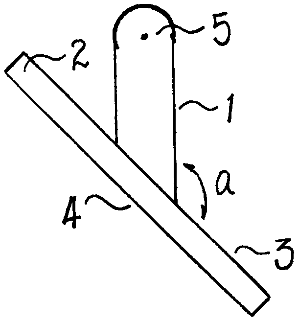
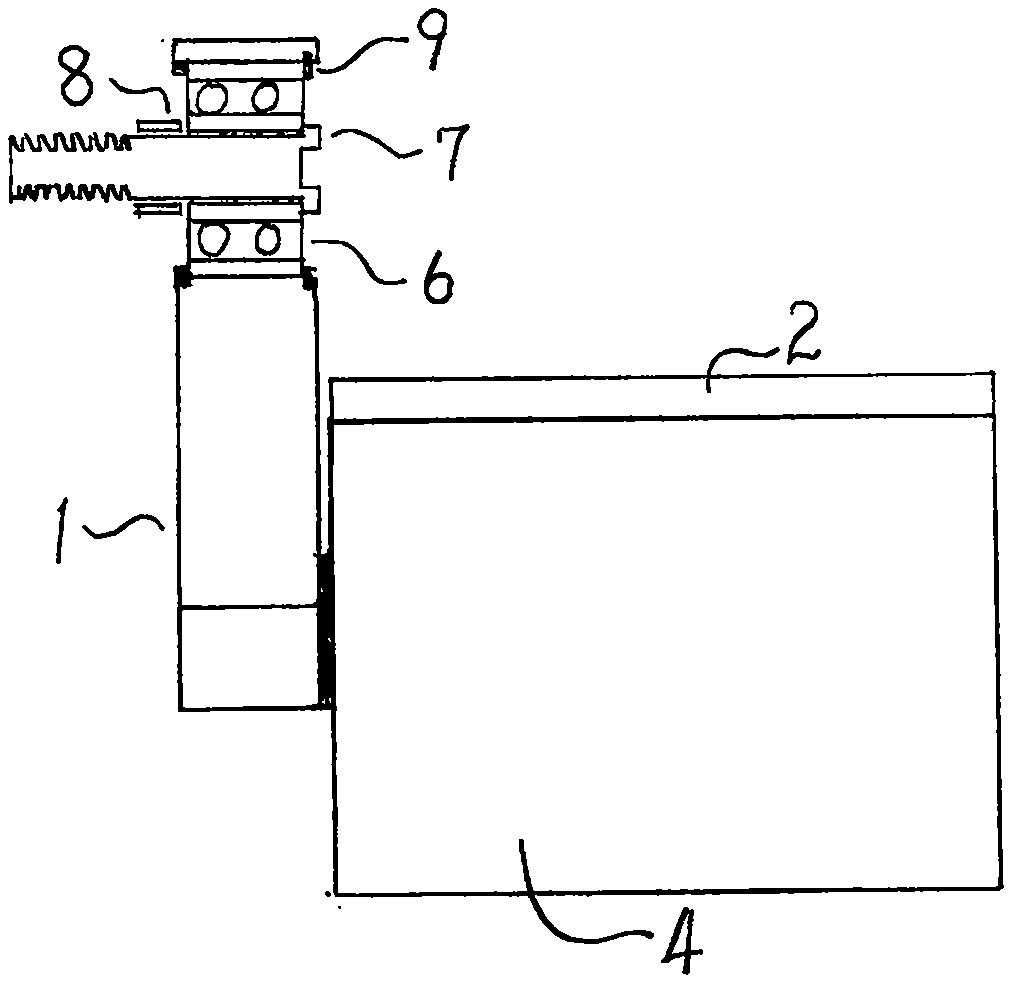
[0013] Such as figure 1 , 2 As shown, one end of the right connecting rod 1 is provided with a bearing 6, and the inner ring of the bearing 6 is covered with a bolt 7. The bolt 7 is screwed into the screw hole of the right crank (not shown). The other end of the right connecting rod 1 is connected to the right foot The pedal 2 is fixedly connected or is an integral structure, and the angle formed by the upper plane 3 of the right pedal and the right connecting rod 1 is 135 degrees.

[0014] Due to its own weight, when the foot is not placed on the right pedal 2, the right pedal device will naturally sag. The upper plane 3 of the pedal is approximately 45 degrees with the ground. When the foot is placed on the right pedal 2 When the upper plane 3 of the foot pedal rotates counterclockwise to a horizontal state, the front swing angle of the right link 1 is about 45 degrees at this time. When riding, if the right pedal 2 is near the highest position, the sole of the foot should be b...


PUM


Abstract

The invention relates to a bicycle pedal device which comprises a left crank and a right crank, connecting rods and pedals, wherein one end of each of the connecting rods is in hinged connection to each of the cranks; and the other end of the connecting rod is directly fixedly connected to each of the pedals. Relevant components used for hinged connection between the connecting rods and the pedalsare cancelled, so the structure is simplified; a large forward swing angle of the connecting rod is obtained; a driving torque obtained on the cranks by the same pedal force is greatly increased; anddriving efficiency is significantly increased.

Description

technical field [0001] The invention relates to the technical field of human-powered bicycles, in particular to a bicycle pedal device. Background technique [0002] The phase difference between the left and right cranks of existing bicycles is 180 degrees. When the pedal on one side runs to the lowest position, the pedal on the other side is at the highest position and is at the dead point of force development. The same pedal force is in the small area of ​​the highest position. The torque formed in the range is small and the driving efficiency is low. In order to increase the torque, a connecting rod pedal device with two hinged shafts has appeared. One end of the connecting rod is hinged with the crank, and the other end is hinged with the pedal. When the pedal moves to the highest position, the foot exerts a downward pressure while exerting a forward swing force, so that the connecting rod obtains a forward swing angle of about 5 degrees, and the increased torque on the ...

Claims


Application Information

Patent Timeline
IPC IPC(8): B62M3/00
CPCB62M3/00
Inventor 王相军
Owner 王相军
Why Eureka
Try Eureka