
Clamping assembly and method for single fuel element under transient irradiation test conditions

A fuel element and clamping assembly technology, applied in the field of irradiation, can solve the problems of maintaining a single fuel element, difficult to maintain a single fuel element, etc., and achieve the effects of keeping fixed, stable, overall strength and safety performance

Active Publication Date: 2021-01-05
NUCLEAR POWER INSTITUTE OF CHINA
View PDF6 Cites 0 Cited by
  • Summary
  • Abstract
  • Description
  • Claims
  • Application Information

AI Technical Summary

Problems solved by technology

[0005] The purpose of the present invention is to provide a clamping assembly and method for a single fuel element under transient irradiation test conditions, so as to solve the problem in the prior art that it is difficult to clamp a single fuel element to meet the transient test requirements , to achieve the purpose of meeting the requirements of high temperature, high pressure and fluid vibration under the test of transient radiation, and maintaining the fixation of a single fuel element

Method used


Image

  • Clamping assembly and method for single fuel element under transient irradiation test conditions
  • Clamping assembly and method for single fuel element under transient irradiation test conditions
  • Clamping assembly and method for single fuel element under transient irradiation test conditions

Examples


Embodiment 1

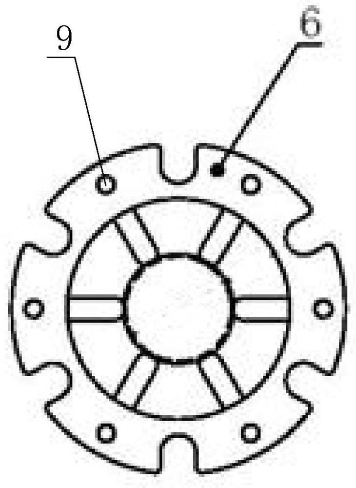
[0039] Such as Figure 1 to Figure 6 The shown clamping assembly for a single fuel element under transient irradiation test conditions includes an upper fixed ring 1, a central grid 3, and a lower fixed ring 5 distributed in sequence. The upper fixed ring 1, the central grid The frame 3 and the lower fixing ring 5 are fixed by several support rods 2; the central grid 3 is used to clamp a single fuel element;

[0040]Preferably, the central grid 3 includes two central fixed rings 6 facing each other, and a number of annularly distributed elastic rods 7 are arranged between the two central fixed rings 6, and the elastic rods 7 have a direction toward the central fixed ring 6 A curved section that is concave in the direction of the axis. Several supporting rods 2 are distributed in a ring, and the circumferences of the upper fixing ring 1 and the lower fixing ring 5 are provided with some fixing holes 8 for fixing the ends of the supporting rods 2, and the center fixing ring 6 i...

Embodiment 2

[0047] The upper fixed ring 1, the lower fixed ring 5 and the center grid 3 are connected by the support rod 2. During assembly, the elastic member 4 is welded to the lower fixed ring 5, and then the support rod 2 is inserted into the fixing hole of the lower fixed ring 5, and then put into the center after welding. Grid 3, the whole assembly is put into two center grids 3, keep a certain distance between them, the place where the support rod 2 contacts the center fixing ring 6 of the center grid 3 is spot welded, and finally the support rod 2 is inserted into the upper fixing ring 1's fixing hole is welded. The whole assembly is connected with each part through the support rod 2, and the contact parts are welded to ensure the overall strength of the grid. The center grid 3 is welded on the support rod 2, and the fuel element is clamped by the elastic rod 7. The end of the fuel element is in contact with the elastic member 4 to avoid damage to the fuel element due to hard con...


PUM


Abstract

The invention discloses a clamping assembly and method for a single fuel element under a transient irradiation test working condition. The clamping assembly comprises an upper end fixing ring, a central grillwork and a lower end fixing ring, wherein the upper end fixing ring, the central grillwork and the lower end fixing ring are sequentially distributed and are fixed through a plurality of supporting rods; the central grillwork is used for clamping a single fuel element; and an elastic piece is arranged at the end, facing the center grillwork, of the lower end fixing ring. The invention aimsto provide the clamping assembly and method for the single fuel element under the transient irradiation test working condition so as to overcome the problem that it is difficult to clamp a single fuel element to meet the requirement of a transient test in the prior art; and the clamping assembly and method can achieve the purposes of meeting the requirements for high temperature, high pressure and fluid vibration in a transient irradiation test and keeping the single fuel element fixed.

Description

technical field [0001] The invention relates to the technical field of irradiation, in particular to a clamping assembly and method for a single fuel element under transient irradiation testing conditions. Background technique [0002] Fuel element is the smallest unit of fuel assembly, usually rod-shaped, composed of pellets, cladding, end plugs, etc. It is the place for fission reaction and the smallest carrier unit for new fuel and material research. [0003] In the field of nuclear power, the research and development of new fuel elements must undergo sufficient theoretical analysis and verification and irradiation tests to prove that they can achieve the expected design indicators and ensure safe and reliable operation within the design life. Among them, the most feasible method of irradiation test is to conduct transient test on the test pile, obtain the behavior data of the fuel element when the power changes, optimize the physical model, analyze the cause of the damag...

Claims


Application Information

Patent Timeline
Patent Type & Authority Patents(China)
IPC IPC(8): G21C17/00G21C17/10
CPCG21C17/00G21C17/10Y02E30/30
Inventor 张帅杨文华汪海
Owner NUCLEAR POWER INSTITUTE OF CHINA
Learn More