Tea drying equipment and process

A drying equipment and tea technology, which is applied in tea treatment before extraction, etc., can solve the problems affecting the drying effect of tea and uneven heating of tea, so as to improve the efficiency of heat utilization, avoid uneven heating and prolong the service life

Inactive Publication Date: 2019-12-20
HUITONG RUICHUN TEA IND CO LTD
View PDF0 Cites 0 Cited by
  • Summary
  • Abstract
  • Description
  • Claims
  • Application Information

AI Technical Summary

Problems solved by technology

[0004] The purpose of the present invention is to solve the problem that the tea leaves are piled up in the drying equipment, and the heating of the tea leaves is not uniform, which affects the drying effect of the tea leaves, and proposes a tea drying equipment and its drying process

Method used


Image

  • Tea drying equipment and process
  • Tea drying equipment and process
  • Tea drying equipment and process

Examples


Embodiment 1

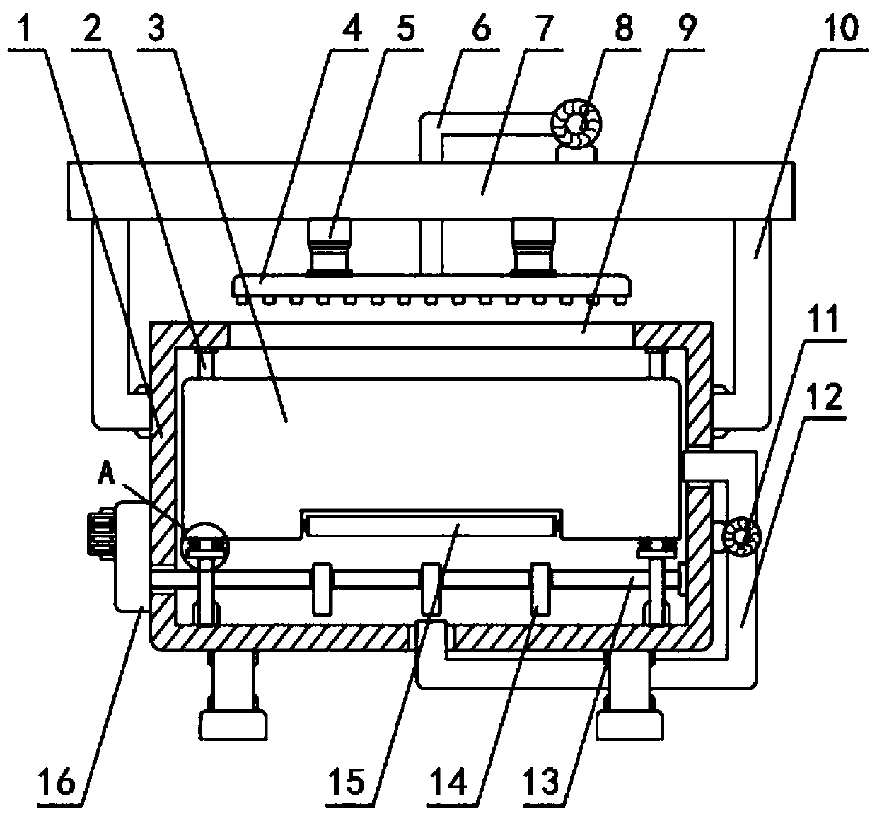
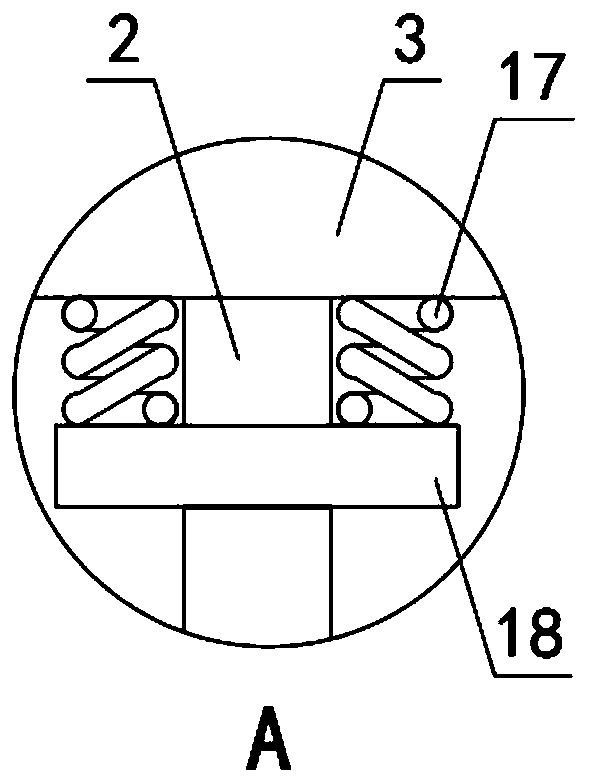
[0037] see Figure 1-4 , a kind of tea drying equipment, comprising a drying box 1, a hot air blower 8, a drying rack 4 and an opening 9, the inside of the drying box 1 is provided with a placement frame 3, and the inner surface wall of the placement frame 3 is fixed with Place the net 20, the place net 20 is used for the placement of tea leaves, the four corners of the placement frame 3 are slidingly embedded with slide bars 2, and the slide bars 2 are fixed between the inner surface walls of the vertical end of the drying box 1. The rod 2 and the placement frame 3 are clearance fit, the placement frame 3 can move in the vertical direction, the slide bar 2 can prevent the displacement of the placement frame 3 in the vertical direction, the placement frame 3 and the drying box 1 A rotating shaft 13 in the horizontal direction is arranged between the inner and outer walls of the bottom, and a cam 14 is sleeved on the rotating shaft 13. The cam 14 and the rotating shaft 13 are i...

Embodiment 2

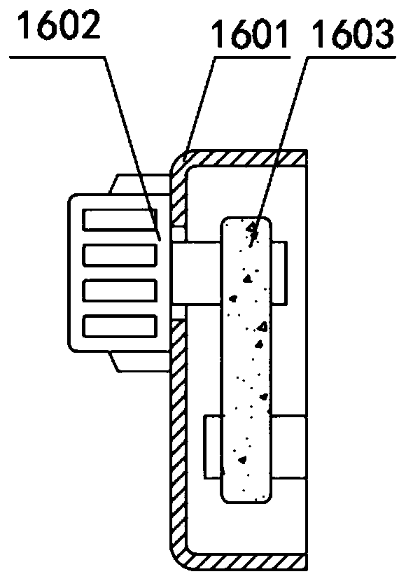
[0039] see figure 2 , the driving mechanism 16 includes a protective cover 1601, a motor 1602 is fixed on the side wall of the protective cover 1601, the rotating shaft 13 runs through the side wall of the drying box 1, and extends to the inner cavity of the protective cover 1601, the output shaft of the motor 1602 and the rotating shaft 13 is connected by a belt 1603 transmission, the output shaft of the motor 1602 can pass the belt 1603 to make the rotating shaft 13 rotate, and the lower surface wall of the placement frame 3 is connected with a rotating roller 15 through the rotating shaft, and the rotating roller 15 avoids the cam 14 and the placement The friction between the lower surface walls of the frame 3 reduces the wear of the placement frame 3 and can effectively improve the service life of the placement frame 3 .

Embodiment 3

[0041] see figure 1 and image 3 , the top of the drying box 1 is fixed with a top plate 7 through the connecting frame 10, the drying frame 4 is located at the bottom of the top plate 7, and an electric telescopic rod 5 is arranged between the drying frame 4 and the top plate 7, and the electric telescopic rod 5 can drive the drying The drying frame 4 moves in the vertical direction, and the inner surface wall of the bottom of the placement frame 3 is provided with a ventilation hole 19, and the outside of the drying box 1 is provided with a circulation pipe 12, and the circulation pipe 12 is embedded in the bottom of the drying box 1 On the inner surface wall and the side wall, an exhaust fan 11 is installed on the circulation pipe 12. Under the action of the exhaust fan 11, the hot air flow can wrap the placement frame 3, which can effectively carry out secondary use of the hot air flow and contribute to Drying of tea leaves.


PUM


Abstract

The invention discloses tea drying equipment comprising a drying box, a hot air blower, a drying rack and an opening. The drying box is internally provided with a placing frame, and a placing net is fixed to the inner surface wall of the placing frame; sliding rods are slidably embedded at the four corners of the placing frame; a rotating shaft in the horizontal direction is arranged between the placing frame and the inner surface wall of the bottom of the drying box, and the rotating shaft is sleeved with a cam; and the cam is connected with the placing frame through a spring elastically. Inthe tea drying equipment, the rotating shaft in the horizontal direction is arranged between the placing frame and the drying box, and the rotating shaft is sleeved with the cam; through arrangement of a motor and a belt, the cam can be driven by the rotating shaft to rotate, and through arrangement of the cam and the spring, the placing frame can be vibrated slightly in the vertical direction; tea can be prevented from being stacked in the placing frame effectively, and the interior and exterior of the tea can be effectively prevented from being heated unevenly; and the tea drying equipment benefits drying of the tea.

Description

technical field [0001] The invention relates to the technical field of tea production and processing, in particular to a tea drying equipment and a drying process thereof. Background technique [0002] Tea originated in China. Tea was first used as a sacrifice, but it has been used as a vegetable since the late Spring and Autumn Period. It was developed into a medicinal drink in the middle of the Western Han Dynasty, and it was developed into a high-grade court drink in the late Western Han Dynasty. It was popularized as a common drink by the people during the Western Jin Dynasty. In the future, the earliest relics of artificially planting tea were found in the Tianluoshan site in Yuyao, Zhejiang. It has a history of more than 6,000 years. Tea drinking began in China. The leaves are leathery, oblong or oval, and can be drunk directly with boiling water. Depending on the variety It can be divided into six categories according to the production method and product shape. Accord...

Claims


Application Information

Patent Timeline
Patent Type & Authority Applications(China)
IPC IPC(8): A23F3/06
CPCA23F3/06
Inventor 杨忠林曾荣华蔡平秀杨庆梁丽娟
Owner HUITONG RUICHUN TEA IND CO LTD
Why Eureka
Try Eureka