Eureka AIR delivers breakthrough ideas for toughest innovation challenges, trusted by R&D personnel around the world.

Grip dynamometer with elastic stabilizing units and palm width adjusting function, and application method of grip dynamometer

An elastic, stable and wide-adjustable technology, applied in the field of hand dynamometers, can solve the problems of limited reproducibility, inconsistent results, and large volume of measuring instruments, and achieve the effects of reducing inaccurate data collection, easy to carry and grasp, and accurate measurement results

Pending Publication Date: 2019-12-20
FUJIAN UNIV OF TECH
View PDF7 Cites 1 Cited by
  • Summary
  • Abstract
  • Description
  • Claims
  • Application Information

AI Technical Summary

Problems solved by technology

However, the traditional measurement methods generally have the following disadvantages: low accuracy of measurement results, large volume of measuring instruments, poor autonomy, etc.
For example, hydraulic grip dynamometers have hysteresis; pneumatic grip dynamometers will give different measurement results due to the different surface areas of the hands of different users; mechanical grip strength measurement methods have inconsistent results due to different measurement positions, so The reproducibility of this method is limited
In addition, these grip dynamometers do not have user interface, cloud data management, etc. functions, which limit the use cases of grip strength assessment

Method used


Image

  • Grip dynamometer with elastic stabilizing units and palm width adjusting function, and application method of grip dynamometer
  • Grip dynamometer with elastic stabilizing units and palm width adjusting function, and application method of grip dynamometer
  • Grip dynamometer with elastic stabilizing units and palm width adjusting function, and application method of grip dynamometer

Examples


Embodiment Construction

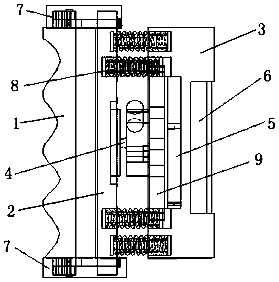
[0036] Such as Figure 1-4 As shown, the grip meter of the present invention with elastic stabilization unit and palm width adjustment function includes a grip 1, a connecting plate 2, a substrate 3, a pressure sensor 4, an integrated circuit board 5 and a battery 6;

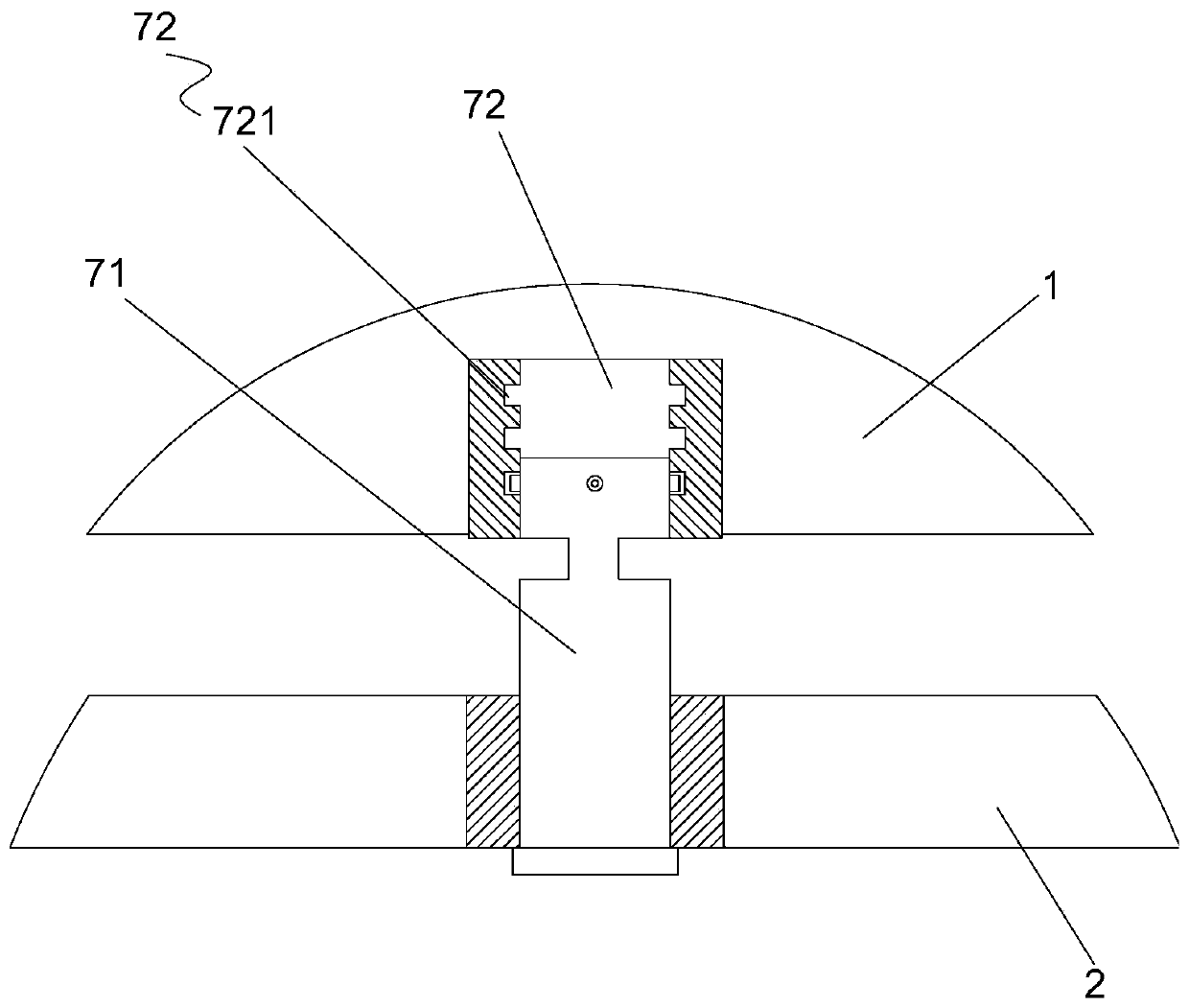
[0037] The two sides of the connecting plate 2 are respectively connected to the grip 1 through a palm width adjusting mechanism 7, and the palm width adjusting mechanism 7 is used to adjust the size of the interval between the grip 1 and the connecting plate 2;

[0038] The pressure sensor 4 is placed in the middle of the connecting plate 2 and the base plate 3, the bottom of the pressure sensor 4 is fixed on the inner surface of the base plate 3, and the detection head of the pressure sensor 4 rests on the inner surface of the connecting plate 2;

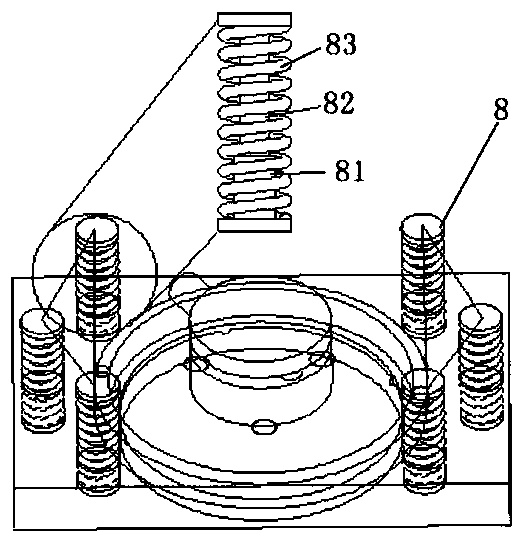
[0039] The connecting plate 2 and the base plate 3 are directly connected with two sets of elastic stable components symmetrically arranged on both sides of the pressure s...


PUM


Abstract

The invention discloses a grip dynamometer with elastic stabilizing units and a palm width adjusting function, and an application method of the grip dynamometer. The grip dynamometer includes a grip,a connection plate, a base plate, a pressure sensor, an integrated circuit plate and a battery. According to the grip dynamometer, novel elastic stabilizing assemblies are designed, through the elastic stabilizing assemblies, a triangular stabilizing layout design is adopted, when forces are exerted at the two ends of the stabilizing units, stabilizing unit main bodies and all column surfaces do not waggle, no negative influences can be caused during grip force measuring, and the direction of stress on the sensor accords with that of a center line of the grip dynamometer. According to the gripdynamometer, a palm width adjusting mechanism is also arranged, therefore, the grip dynamometer can adapt to the widths of palms of users by adjusting the structures of parts during measurement, theusers conveniently grasp the grip dynamometer, and the situations are avoided that the grip dynamometer falls off from hands during measurement, and the inappropriate size of the grip of the grip dynamometer influences force application of the users; and thus, the situation is ensured that measurement processes are conducted stably, and measurement results are more accurate.

Description

Technical field [0001] The present invention relates to the field of grip dynamometers, in particular to a grip dynamometer with elastic stabilization unit and palm width adjustment function and its use method. Background technique [0002] Grip strength has the characteristics of easy measurement and stable performance, so it is often used to evaluate the related functions of muscles. At present, traditional grip strength measurement tools include hydraulic, pneumatic and mechanical types. However, traditional measurement methods generally have the following shortcomings: low accuracy of measurement results, large measuring instruments, and poor autonomy. For example, hydraulic grip dynamometers have hysteresis; pneumatic grip dynamometers may obtain large differences in measurement results due to the different surface areas of the hands of different users; mechanical grip strength measurement methods cause inconsistent results due to different measurement positions, so The re...

Claims


Application Information

Patent Timeline
Patent Type & Authority Applications(China)
IPC IPC(8): A61B5/22
CPCA61B5/225A61B5/0004A61B5/0022
Inventor 罗堪赖智晨黄炳法张茂林李建兴马莹陈炜
Owner FUJIAN UNIV OF TECH
Why Eureka
Eureka Blog
Learn More