Mixing barrel locking mechanism, automatic locking system and automatic mixing system

A locking mechanism and automatic locking technology, applied in mixers, mixers with rotating containers, mixer accessories, etc., can solve problems such as laboriousness, loose pressure plates, production accidents, etc., to reduce the risk of production accidents and avoid failures High rate and the effect of preventing production accidents

Active Publication Date: 2019-12-20
国机智能技术研究院有限公司
View PDF7 Cites 2 Cited by
  • Summary
  • Abstract
  • Description
  • Claims
  • Application Information

AI Technical Summary

Problems solved by technology

This structure is time-consuming and labor-intensive. Due to the difference in manual tightening torque, once the screw tightening force is small and the pressure plate is loose during the mixing process

Method used


Image

  • Mixing barrel locking mechanism, automatic locking system and automatic mixing system
  • Mixing barrel locking mechanism, automatic locking system and automatic mixing system
  • Mixing barrel locking mechanism, automatic locking system and automatic mixing system

Examples


Embodiment 1

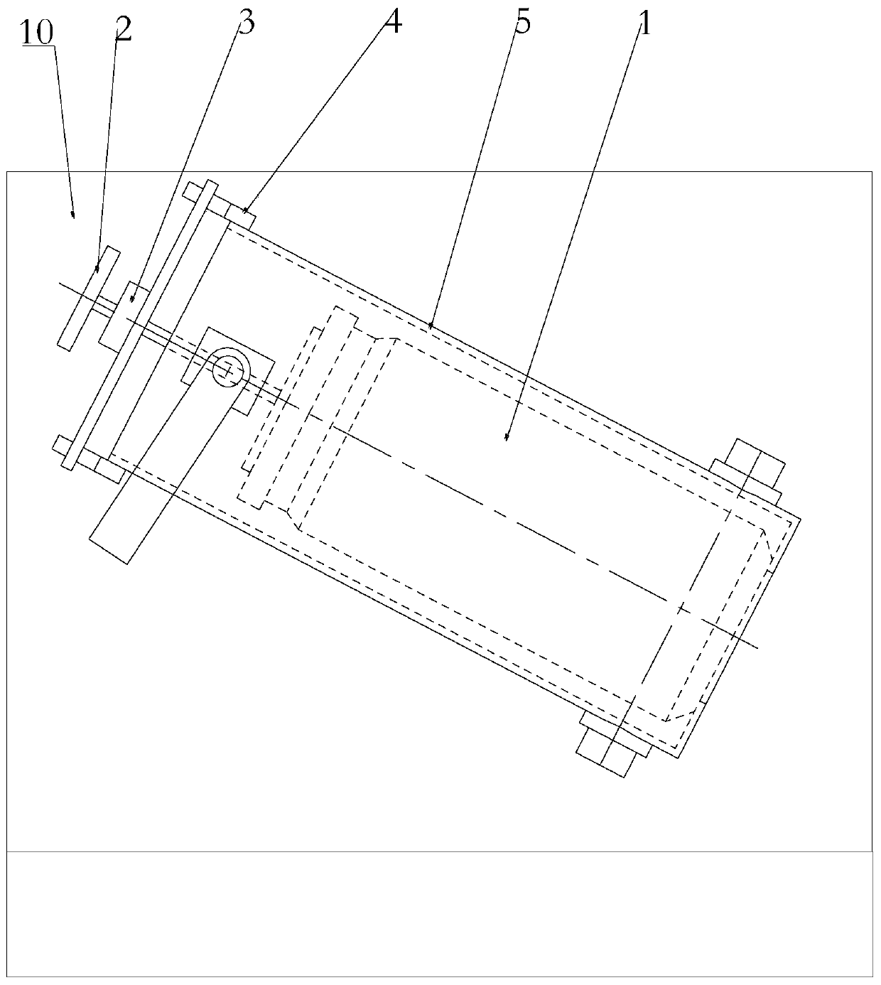
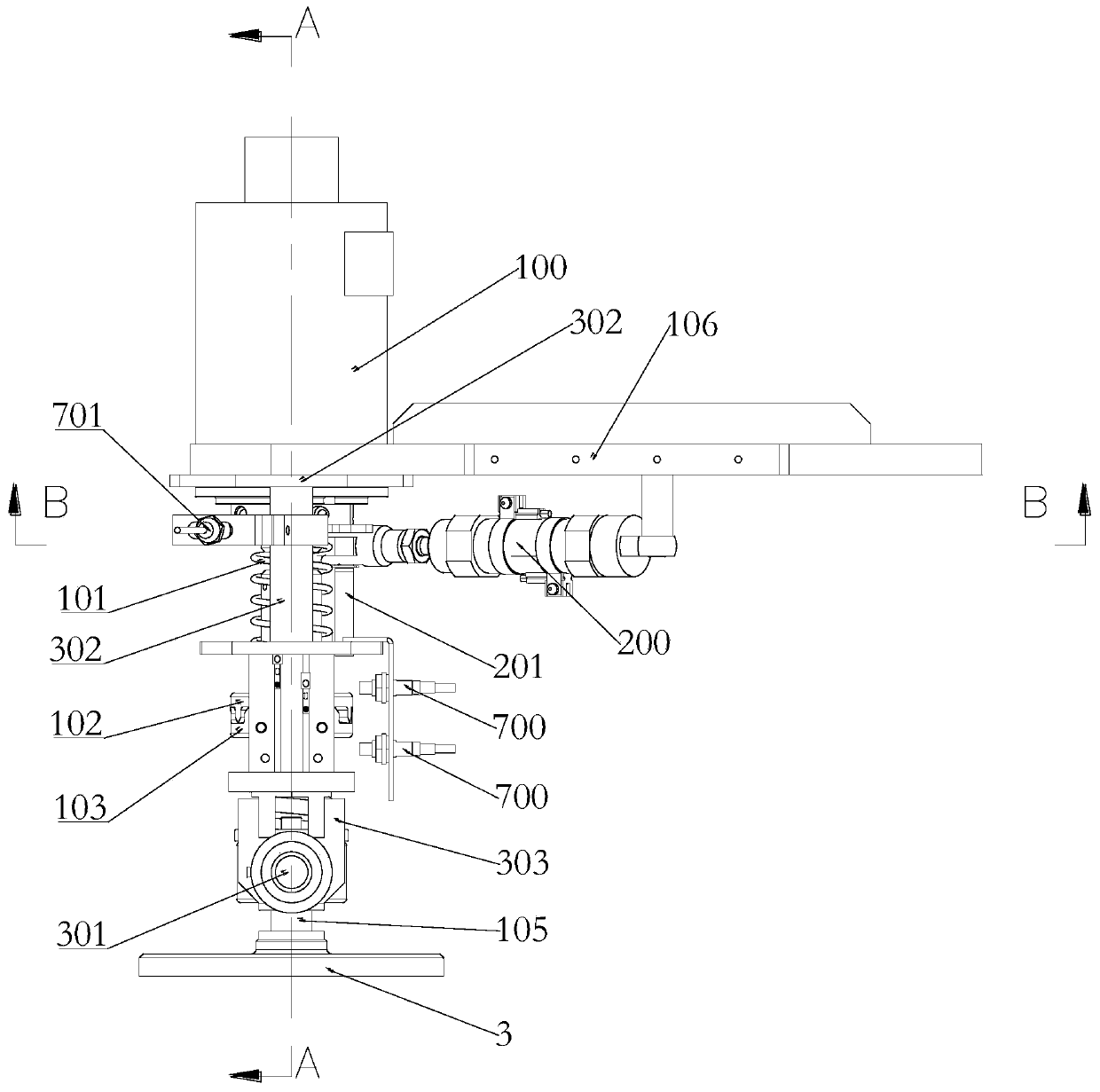
[0047] like Figure 3-Figure 12 As shown, a mixing tank locking mechanism of this embodiment is used to lock the mixing tank 1 in the mixing frame 5; it includes a driving device 100, a driving device 200, a clamping device 300, a lock Locking pin shaft 301 and locking screw rod 105, the clamping device 300 is used to clamp or release the locking pin shaft 301, the locking screw rod 105 passes through and is threadedly connected to the locking pin shaft 301 , the driving device 100 is installed on the clamping device 300 and drives the locking screw 105 to retract or extend from the locking pin 301; wherein, the driving device 2 200 drives the The clamping device 300 moves and the locking pin 301 is snapped into or out of the mixing frame 5, and when the driving device 100 drives the locking screw 105 to stretch out and compress the mixing bucket 1, the The clamping device 300 releases the locking pin 301 .

[0048] In this embodiment, the driving device 1 and the driving de...

Embodiment 2

[0061] like Figure 7-Figure 12As shown, an automatic locking system for a mixing tank in this embodiment provides an automatic system for the locking mechanism in Embodiment 1, including the locking mechanism, telescopic sensor 700, and rotation detection sensor 701 and a PLC controller, the telescopic sensor 700 and the rotation detection sensor 701 are installed on the clamping device 300 respectively, and the telescopic sensor 700 and the rotation detection sensor 701 are used to respectively collect the The position information and rotation information of the drive shaft 104 are sent to the PLC controller, and the PLC controller is used to control the clamping device when the drive shaft 104 stops rotating and the drive shaft 104 reaches a preset position 300 to release the locking pin 301 .

[0062] A specific scheme of this embodiment is, as Figure 5 As shown, the drive shaft 104 is sleeved with a detection ratchet 702 that rotates synchronously with it, and the dete...

Embodiment 3

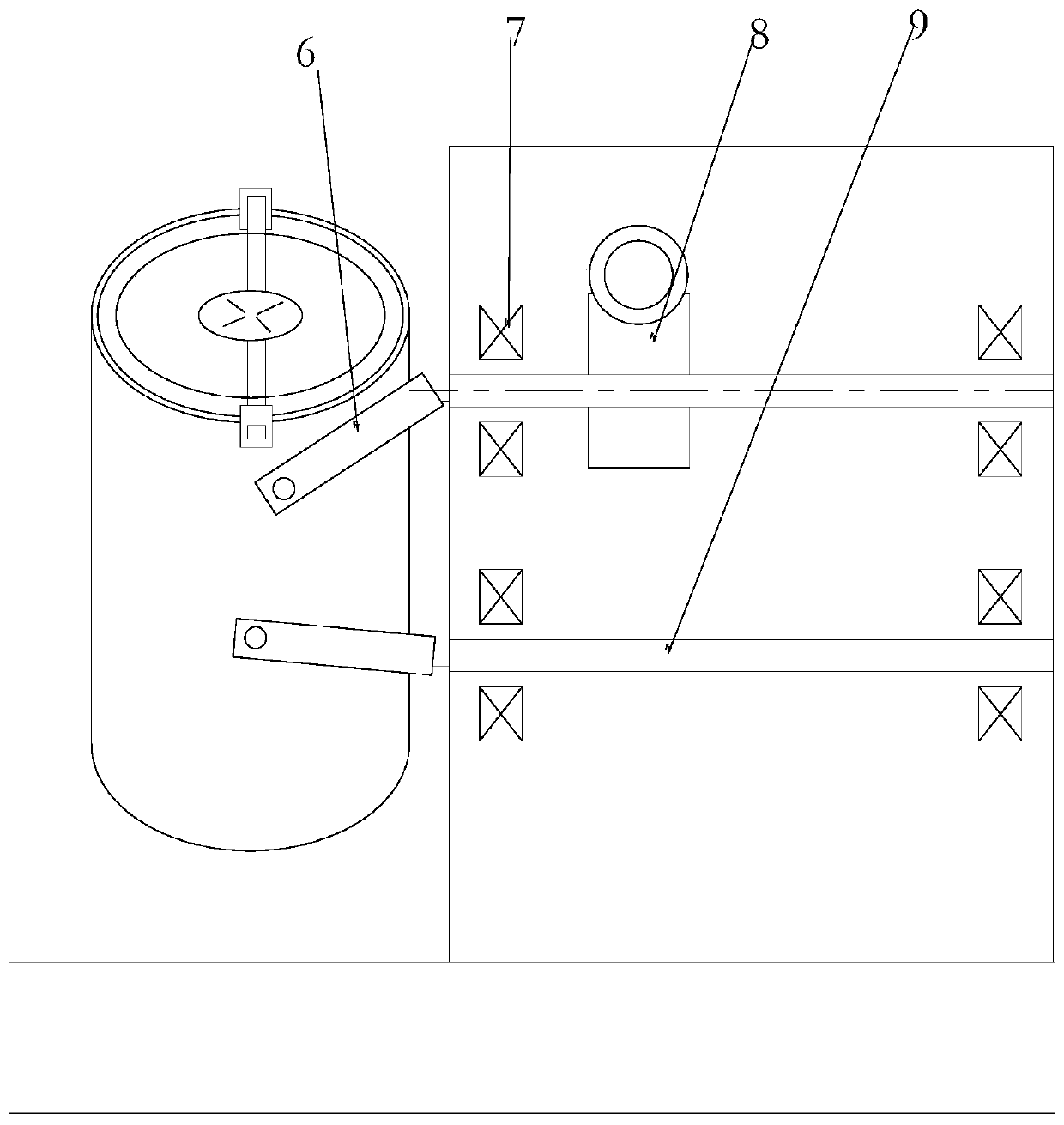
[0065] like Figure 7-Figure 12 As shown, an automatic mixing system for a mixing tank in this embodiment includes the automatic locking system, and also includes a driving device 4800, an origin sensor 801, a mixing frame 5 and a photoelectric sensor. The origin sensor 801 It is used to collect the position information of the mixing frame 5 and send it to the PLC controller, and the PLC controller is used to control the driving end extension of the driving device 4800 when the mixing frame 5 is at the origin position. Entering into the mixing frame 5 provides support for the mixing bucket 1 to be put into the mixing frame 5 . It also includes lifting cylinder 2 802, articulated arm 803 and articulated seat 804, the lift cylinder 2 802 and articulated arm 803 are respectively hinged on the articulated seat 804, and the driving device 4 800 is installed on the articulated arm 803, The driving end of the lift cylinder 2 802 is hinged to the articulated arm 803 and drives the ar...


PUM


Abstract

The invention relates to a mixing barrel locking mechanism, an automatic locking system and an automatic mixing system, the locking mechanism is used for locking the mixing barrel in a mixing frame; the locking mechanism comprises a first driving device, a second driving device, a clamping device, a locking pin shaft and a locking screw rod, the clamping device is used for clamping or releasing the locking pin shaft, the locking screw rod penetrates through and is connected to the locking pin shaft in a threaded mode, and the first driving device is installed on the clamping device and drivesthe locking screw rod to retract or extend from the locking pin shaft; the second driving device drives the clamping device to move and clamps the locking pin shaft into or out of the mixing frame, and when the first driving device drives the locking screw rod to extend and compress the mixing barrel, the clamping device releases the locking pin shaft. According to the mixing barrel locking mechanism, the automatic locking system and the automatic mixing system, matching of the first driving device and the second driving device is utilized, the locking screw rod extends out of the locking pinshaft and compresses the mixing barrel, a constant preload on the mixing barrel is maintained, and the production accident caused by the difference of the manual tightening torque is prevented.

Description

technical field [0001] The invention relates to a mixing barrel locking mechanism, an automatic locking system and an automatic mixing system. Background technique [0002] At present, many mixers used for mixing powder materials need to manually load and disassemble the mixing tank. The general structure uses a pressure plate to press the mixing tank, and the screw on the pressure plate is manually tightened to make the pressure plate in the mixing tank. Lock between the material barrel and the mixing frame. like figure 1 and figure 2 As shown, the working principle of the existing mixing structure is that the drive motor assembly 8 in the mixer drives the rocker arm 6 of the mixing frame to rotate, and the rotation of the rocker arm 6 of the two sets of mixing frames drives the 360-degree vortex rotation of the mixing frame 5 to generate For the action effect of mixing, the driving shaft and the driven shaft 9 of the drive motor assembly 8 are respectively installed in...

Claims


Application Information

Patent Timeline
IPC IPC(8): B01F9/02B01F9/00B25B27/14B01F29/60
CPCB25B27/14B01F29/34B01F29/60B01F35/42
Inventor 刘思鹏林晓东林青易国春
Owner 国机智能技术研究院有限公司
Why Eureka
Try Eureka