A wall cutter bracket

A cutting machine and bracket technology, which is applied in the manufacture of tools, work accessories, stone processing equipment, etc., can solve the problems of taking up a lot of space, consuming a lot of physical strength, and unstable center of gravity, so as to achieve high work efficiency, reduce falling force, The effect of improving safety

Active Publication Date: 2021-09-03
孙艳
View PDF11 Cites 0 Cited by
  • Summary
  • Abstract
  • Description
  • Claims
  • Application Information

AI Technical Summary

Problems solved by technology

[0002] With the rapid development of China's real estate industry, it is necessary to install water and electricity pipes in house construction, and it is necessary to cut out reserved grooves on the vertical wall. The traditional method is to manually use a groove cutting machine to move the groove on the wall. However, it is difficult to hold the heavy cutting machine in hand. At the same time, due to the obstruction of the vision due to the dust, the depth of the cut groove is uneven, and the cutting track is not straight. It requires great physical strength and low efficiency when cutting, and the work quality cannot meet the specified requirements. It is not conducive to the installation of pipelines by plumbers in the later stage; in the existing technology, new technologies and mechanical equipment are also applied in the cutting of building construction walls, such as the national invention patent "a vertical wall cutting device in building construction" ( Patent No.: 201610764517.7) provides a cutting frame, which slides on the double vertical bars to install the horizontal bars that move up and down, and slides left and right on the horizontal bars to install the cutting machine. There are problems such as large and bulky, taking up a lot of space, unstable center of gravity, poor safety, complex structure and high cost. This kind of equipment is only suitable for large places and large unit construction applications, and many individual constructors cannot use it due to conditions, so it is necessary to innovate a new type of equipment. Inexpensive and high-efficiency construction equipment can change the current situation of high labor intensity, poor quality, low efficiency and poor safety in grooving in the existing technology

Method used


Image

  • A wall cutter bracket
  • A wall cutter bracket
  • A wall cutter bracket

Examples


Embodiment Construction

[0025] In order to make the purpose, technical scheme and advantages of the present invention clearly understood, now in conjunction with the attached Figure 1-10 The present invention will be described in detail.

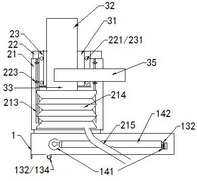
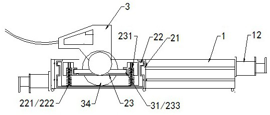
[0026] For the convenience of expression, the structural orientation of the bracket and the sliding box is determined as the front plate, the rear plate, the upper plate, the lower plate, and the two ends as the end plates.

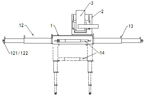
[0027] Such as figure 1 As shown, a bracket for a wall cutting machine includes a bracket 1 and a sliding box 2, the bracket 1 moves and installs the sliding box 2 in the upper plate slideway 10, and the inherent cutting machine 3 is inserted in the sliding box.

[0028] 1. Holder.

[0029] Such as Figure 5 Figure 7 Figure 8 As shown, the bracket 1 is a horizontal rectangular columnar body. The upper plate of the bracket is provided with a slideway 10 parallel to the long side, the slideway is an indented groove or a protruding clip,...


PUM


Abstract

The wall cutting machine bracket includes a bracket and a sliding box. It is characterized in that: the lower end clamp of the sliding box is slidably installed in the upper plate slideway of the bracket, and the two ends of the rear plate of the sliding box are fixedly connected to the vertical frame with elastic parts. The variable-diameter through-pipe that is fixedly connected to the corresponding position of the vertical column on the elastic pressure plate is fastened on the vertical column, and the edge of the bottom plate of the cutting machine is clamped in the slot of the elastic pressure plate and can be elastically pressed forward and backward. The head of the cutting machine slices Located in the slicing port at the lower end of the back plate of the slide box, the present invention installs a movable slide box through the slideway of the upper plate of the bracket, and the cutting machine built in the slide box can be adjusted up and down or spring pressed back and forth, and can cut groove lines of different heights , the depth of the groove can be controlled, and the cutting can run in a straight line; the sliding box moves back and forth on the bracket, and the bracket runs on the telescopic rod that is fixed on the wall and can be extended and retracted, and the telescopic rod of the bracket is vertically clamped And the wheel is pushed on the ground, and the bottom end of the telescopic rod of the bracket is clamped to the wall, and the taper nail of the bracket or the friction mode between the turntable and the wall reduces the falling force of the cutting machine and saves physical strength.

Description

technical field [0001] The invention relates to the technical field of building construction equipment, in particular to a cutting machine bracket for wall surface cutting. Background technique [0002] With the rapid development of China's real estate industry, it is necessary to install water and electricity pipes in house construction, and it is necessary to cut out reserved grooves on the vertical wall. The traditional method is to manually use a groove cutting machine to move the groove on the wall. However, it is difficult to hold the heavy cutting machine in hand. At the same time, due to the obstruction of the vision due to the dust, the depth of the cut groove is uneven, and the cutting track is not straight. It requires great physical strength and low efficiency when cutting, and the work quality cannot meet the specified requirements. It is not conducive to the installation of pipelines by plumbers in the later stage; in the existing technology, new technologies a...

Claims


Application Information

Patent Timeline
Patent Type & Authority Patents(China)
IPC IPC(8): B28D7/00B28D7/02
CPCB28D7/00B28D7/02
Inventor 孙艳
Owner 孙艳
Why Eureka
Try Eureka