A locomotive bogie

A locomotive bogie and frame technology, which is applied in the direction of the bogie, the device for lateral relative movement between the underframe and the bogie, the parts of the railway car body, etc. Large, inconvenient to carry with the vehicle, etc., to achieve the effect of good safety and stability of the locomotive, simple and reliable structure, and good dynamic limit utilization.

Active Publication Date: 2020-11-27
ZHUZHOU ELECTRIC LOCOMOTIVE CO LTD
View PDF5 Cites 0 Cited by
  • Summary
  • Abstract
  • Description
  • Claims
  • Application Information

AI Technical Summary

Problems solved by technology

[0003] So far, the two-axle bogies of locomotives in my country still have the following problems: (1) The middle part of the side beams of the two-axle bogies generally adopts a concave structure, and the longitudinal arrangement of the secondary spring groups requires a large longitudinal space, so the longitudinal arrangement The three sets of steel springs are very difficult in terms of structural space. In addition, when the secondary springs are arranged longitudinally, the distance between the springs and the center of the bogie is farther, so the bogie has a greater resistance to the rotation of the bogie, which is not conducive to the curve passing; (2) Two-axle bogie When the secondary spring group is arranged laterally, since the distance between the inner spring and the center of the bogie is small, the anti-roll stiffness of the car body is small, which is not conducive to meeting the dynamic limit requirements; (3) the existing locomotive two-axle bogie The overall hoisting method generally adopts the method of temporarily wrapping the steel wire rope around the outer end cover of the axle box and hanging it to the side beam of the car body when lifting. In addition, in Europe and other regions, it is not recommended to temporarily install wire rope lifting solutions

Method used


Image

  • A locomotive bogie
  • A locomotive bogie
  • A locomotive bogie

Examples


Embodiment Construction

[0028] The present invention will be described in further detail below in conjunction with the accompanying drawings.

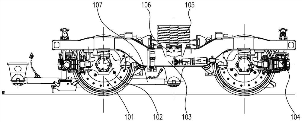
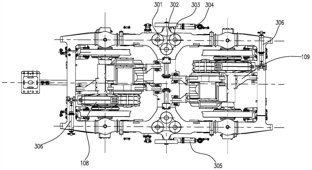
[0029] Such as Figure 1-2 As shown, the B0 bogie of the present invention includes wheel set assembly 101, primary suspension 102, frame 103, foundation braking device 104, secondary suspension 105, integral lifting device 106, traction device 107, driving device 108, driving unit suspension device 109.

[0030] Wheelset assembly 101 adopts integral rolled steel wheels and hollow axles. The integral rolled steel wheels have good integrity and can effectively avoid jumping wheels caused by high-speed operating loads; hollow axles can significantly reduce the axle mass while ensuring strength, so it is also The unsprung mass of the first series is reduced, which is very beneficial to reduce the wheel-rail force during high-speed operation.

[0031] The driving device 108 adopts a non-load-bearing gearbox; the driving torque is transmitted from the pinion to ...


PUM


Abstract

The invention discloses a locomotive bogie. The locomotive bogie comprises a framework shaped like a Chinese character 'ri', the framework comprises two side beams, one horizontal beam and two end beams, the middle portions of the side beams adopt concave structures, the locomotive bogie is characterized in that the upper surface of the middle portion of each side beam is provided with three steelsprings, the three steel springs are distributed at three vertices of an isosceles triangle, the bottom edge of the isosceles triangle is parallel to the longitudinal direction of the side beams, andan apex angle of the isosceles triangle is closer to the center of the framework than base angles. According to the locomotive bogie, two-series spring group triangle arrangement is adopted, spaces of biaxial bogie side beam middle portion concaving and being connected with the framework middle horizontal beam are utilized sufficiently, triangular arrangement can obtain less bogie head-shaking rotating resistance than longitudinal arrangement and larger vehicle body side rolling resistant stiffness than horizontal arrangement, therefore, by means of the locomotive bogie, good curve passing performance and dynamic limit utilization degree can be obtained.

Description

technical field [0001] The invention relates to a locomotive bogie and belongs to the technical field of rail vehicle bogies. Background technique [0002] There are many locomotives using two-axle bogies in Europe, and the overall technology and component technology of the two-axle bogies are constantly improving, and the technology is relatively mature. For China, on the basis of summarizing the quasi-high-speed locomotive bogies such as SS8, we have developed two-axle bogies for medium- and high-speed locomotives such as Aoxing, Lanjian, China Star, locomotives exported to Kazakhstan, and FXD1 locomotives. The successful development of these bogies has laid a relatively solid technical foundation for the development of my country's medium and high-speed locomotive bogie technology. [0003] So far, the two-axle bogies of locomotives in my country still have the following problems: (1) The middle part of the side beams of the two-axle bogies generally adopts a concave str...

Claims


Application Information

Patent Timeline
Patent Type & Authority Patents(China)
IPC IPC(8): B61F5/52B61F5/06
CPCB61F5/06B61F5/52
Inventor 邓小星沈龙江李冠军陈国胜曾艳梅王志明刘金菊祝贺汪彦宏李鸿浩李燕慧于海航喻佳文伍玉刚罗汉
Owner ZHUZHOU ELECTRIC LOCOMOTIVE CO LTD
Why Eureka
Try Eureka