Auxiliary frame structure

A sub-frame and body technology, applied in the field of sub-frame structure, can solve the problems of high cost, failure to ensure the installation stability of sub-frame and suspension system, bolt slippage, etc.

Active Publication Date: 2019-12-20
CHERY AUTOMOBILE CO LTD
View PDF6 Cites 3 Cited by
  • Summary
  • Abstract
  • Description
  • Claims
  • Application Information

AI Technical Summary

Problems solved by technology

The sub-frame is usually welded by fully extruded aluminum profiles. Since the mounting surface of the sub-frame connected to the body floor and longitudinal beams is machined after welding, the surface is smooth and the friction coefficient is small. When the vehicle encounters an emergency If the vehicle passes the deceleration belt at a speed of about 40Km / h while stepping on the brakes and turning the direction (to avoid the emergency braking vehicle in front at the intersection), the whole vehicle is subject to a large longitudinal impact force, and the chassis sub-frame and the body are clamped Insufficient force will lead to problems of bolt slippage and abnormal noise due to excessive load on the sub-frame installation point under this extreme working condition, and the installation stability of the sub-frame and suspension system cannot be well guaranteed
In order to solve the problem of abnormal slippage, the current solution is to add a knurled sleeve 2 at the position of the vehicle body mounting point on the subframe 1, such as figure 1 , figure 2 As shown, the hobbing end surface 2a of the knurled sleeve 2 abuts against the bottom of the vehicle body to increase friction and effective clamping force, but the connection method and processing technology of the knurled sleeve 2 are complicated and costly

Method used


Image

  • Auxiliary frame structure
  • Auxiliary frame structure
  • Auxiliary frame structure

Examples


Embodiment Construction

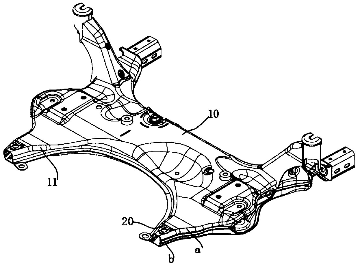
[0012] like Figure 3-Figure 6 As shown, a sub-frame structure includes a sub-frame body 10, and support arms 11 are symmetrically arranged on the left and right sides of the sub-frame body 10, and ball spacers 20 are arranged on the support arms 11, and the ball spacers 20 It includes a gasket body 21 fixedly connected to the support arm 11 , on which a steel ball 23 is riveted, and the steel ball 23 protrudes from the upper surface of the gasket body 21 . After the gasket body 21 is installed on the support arm 11, it is tightened with the vehicle body, and the steel ball 23 is engaged with the body sheet metal and the upper plate of the sub-frame under relatively high pressure, thereby ensuring that the sub-frame is relatively large relative to the vehicle body. There is no abnormal slipping noise under the impact load, which can well ensure the installation stability of the sub-frame and suspension system.

[0013] The spacer body 21 is in the shape of an annular plate as...


PUM


Abstract

The invention aims to provide an auxiliary frame structure capable of solving bolt slippage and abnormal sound and simple in structure. The auxiliary frame structure comprises an auxiliary frame body,wherein supporting arms are symmetrically arranged on the left side and the right side of the auxiliary frame body, ball gaskets are arranged on the supporting arms, the ball gaskets comprises gasketbodies fixedly connected with the supporting arms, steel balls are pressed and riveted on the gasket bodies, and the steel balls protrude out of the upper surfaces of the gasket bodies. In the scheme, after the gasket bodies are arranged on the supporting arms, the gasket bodies are tightly snapped with a vehicle body in a matched mode, and the steel balls, a vehicle body plate and an auxiliary frame upper plate are snapped together at higher pressure, so that the auxiliary frame does not generate slippage and abnormal sound under a large impact load relative to the vehicle body.

Description

technical field [0001] The invention relates to the technical field of automobile parts, in particular to a sub-frame structure. Background technique [0002] The sub-frame of a car can be regarded as the skeleton of the front and rear axles. As a component of the front and rear axles, it can support the front and rear axles and suspension brackets, so that the axles and suspension brackets can be connected to the body through it. The sub-frame is usually welded by fully extruded aluminum profiles. Since the mounting surface of the sub-frame connected to the body floor and longitudinal beams is machined after welding, the surface is smooth and the friction coefficient is small. When the vehicle encounters an emergency If the vehicle passes the deceleration belt at a speed of about 40Km / h while stepping on the brakes and turning the direction (to avoid the emergency braking vehicle in front at the intersection), the whole vehicle is subject to a large longitudinal impact forc...

Claims


Application Information

Patent Timeline
Patent Type & Authority Applications(China)
IPC IPC(8): B62D21/11
CPCB62D21/11
Inventor 朱硕杨方苑潇涵林日根张兵舰
Owner CHERY AUTOMOBILE CO LTD
Why Eureka
Try Eureka