
Beacon light with cooling function for guiding ship to sail

A technology for beacon lights and functions, applied in the field of beacon lights, can solve the problems of high air humidity, reduced practicality of photovoltaic panels, affecting the lighting effect of beacon lights, etc., and achieves the effect of prolonging service life and improving practicability.

Inactive Publication Date: 2019-12-20
方彐云
View PDF9 Cites 4 Cited by
  • Summary
  • Abstract
  • Description
  • Claims
  • Application Information

AI Technical Summary

Problems solved by technology

[0003] However, in the existing marine beacon lights, because the bulb works inside the closed lamp shell, the heat generated by the bulb is difficult to dissipate from the inside of the lamp shell quickly, resulting in the accumulation of heat inside the lamp shell, the temperature gradually rises, and it is easy to shorten the bulb. The service life of the navigation light is long, and when the navigation light is operating at sea, the surrounding air humidity is high, and water mist is easy to form on the surface of the lamp shell, which blocks the transmission of light and affects the lighting effect of the navigation light. Not only that, but in the existing navigation light, in order to To achieve energy saving and environmental protection of equipment through self-power supply, many photovoltaic panels are installed in the metropolis, but these photovoltaic panels are arranged around the equipment in an oblique manner, which causes some photovoltaic panels to fail to receive sunlight normally, affecting the efficiency of photovoltaic power generation, which in turn leads to Some photovoltaic panels are less practical

Method used


Image

  • Beacon light with cooling function for guiding ship to sail
  • Beacon light with cooling function for guiding ship to sail
  • Beacon light with cooling function for guiding ship to sail

Examples


Embodiment Construction

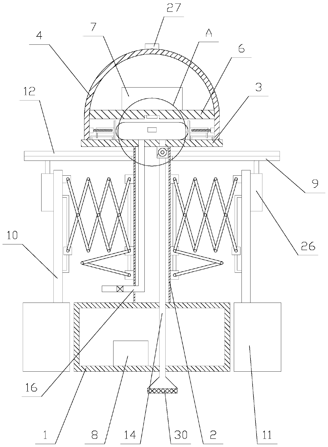
[0024] The present invention is described in further detail now in conjunction with accompanying drawing. These drawings are all simplified schematic diagrams, which only illustrate the basic structure of the present invention in a schematic manner, so they only show the configurations related to the present invention.

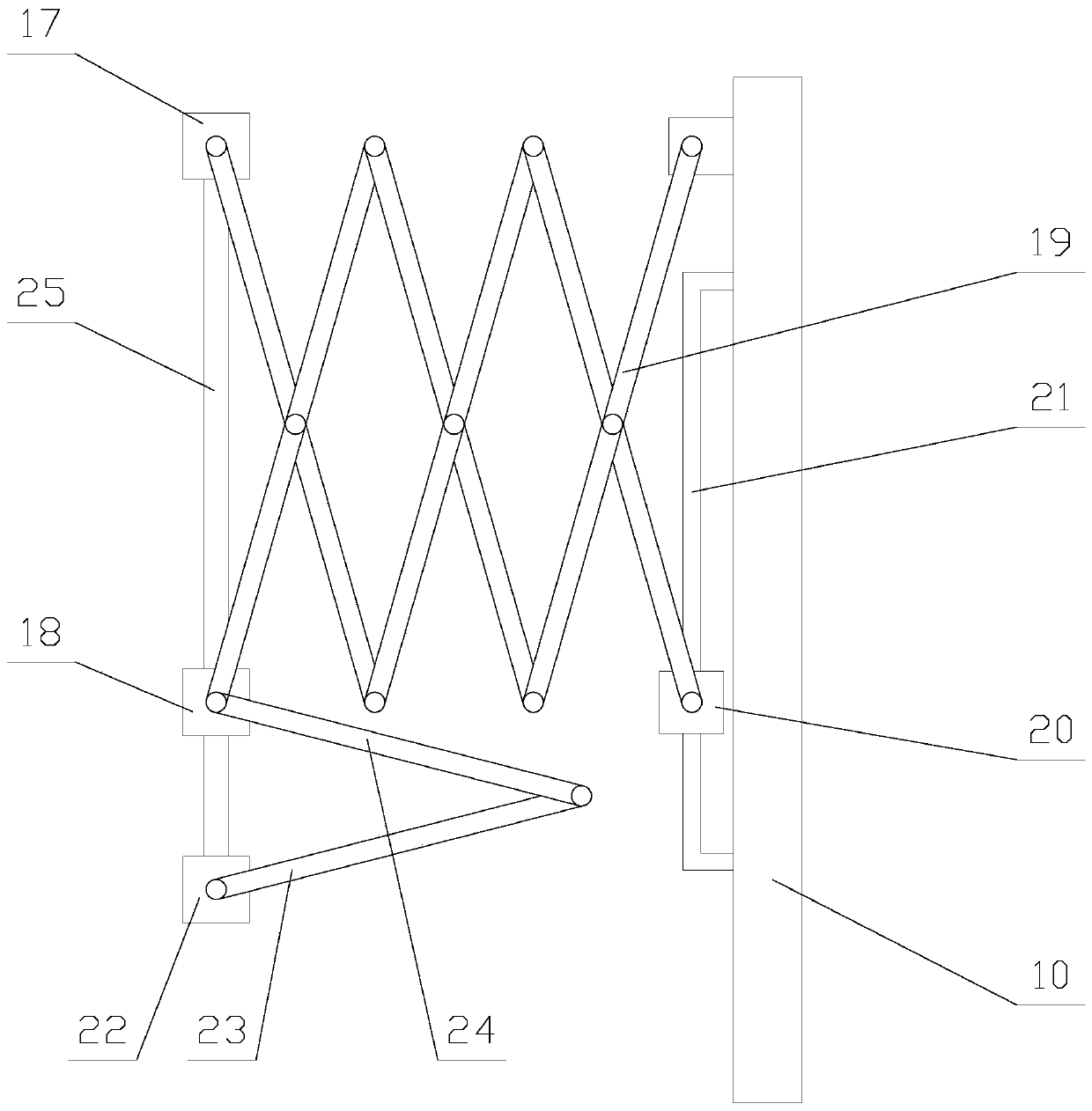
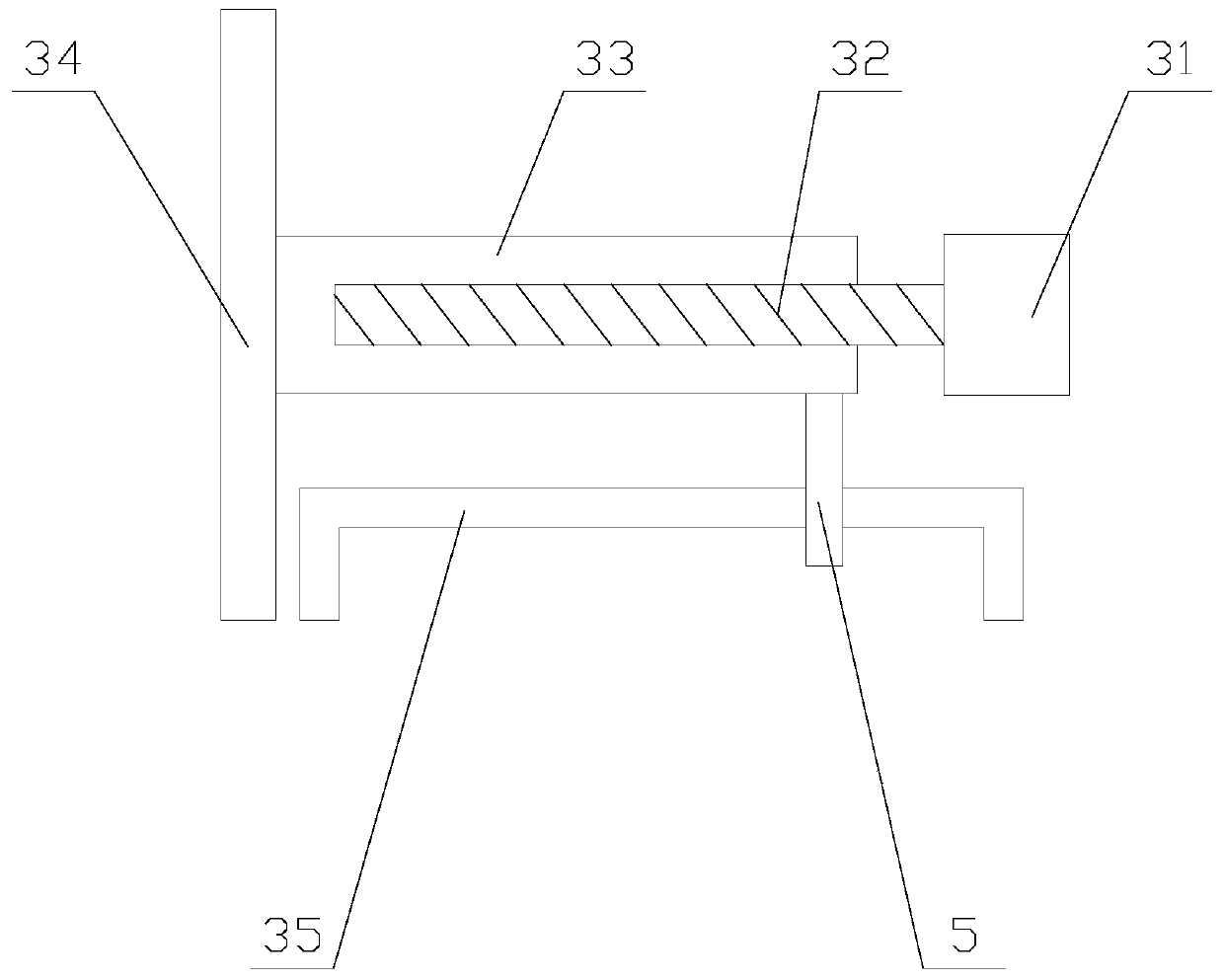
[0025] Such as figure 1 As shown, a navigation light with cooling function for guiding ships to sail, including a first floating block 1, a hollow tube 2, a fixed plate 3, a lamp housing 4, a base plate 6, a lamp bead 7, a processor 8, a cooling mechanism and several The power generation mechanism, the fixed plate 3 is fixed above the first floating block 1 through the hollow tube 2, the first floating block 1 is provided with a cavity, the processor 8 is fixed in the cavity, and the processor 8 is provided with an antenna and a PLC, the lamp housing 4 is fixed above the fixed plate 3, the outer periphery of the substrate 6 is fixed on the inside of the lamp ...


PUM


Abstract

The invention relates to a beacon light with a cooling function for guiding a ship to sail. The beacon light comprises a first floating block, a hollow pipe, a fixed plate, a light shell, a base plate, a light bead, a processor, a cooling mechanism and a plurality of electricity generating mechanisms. Each electricity generating mechanism comprises a photovoltaic panel, a telescopic assembly, a vertical plate, a second floating block, a lifting unit and a baffle plate. The cooling mechanism comprises a water bag, a water pumping pipe, a water pump, a drainage pipe and a plurality of extrudingassemblies. The beacon light with the cooling function for guiding the ship to sail can perform photovoltaic power generation through the electricity generating mechanisms and reserve equipment operating electric energy, and protect the photovoltaic panels in rainfall. The equipment can be also stably supported. Furthermore, seawater in the water bag can be replaced through the cooling mechanism.Heat of the base plate and the light bead is absorbed and the base plate and the light bead are cooled, so that the service life of the light bead is prolonged and the practicality of the equipment isimproved.

Description

technical field [0001] The invention relates to the field of lighting equipment, in particular to a navigation light with cooling function for guiding ships to sail. Background technique [0002] Navigation light is a kind of traffic light installed on certain navigation marks to ensure the safe navigation of ships at night or in heavy fog. It can emit lights and flashes of fixed color and frequency at night or in heavy fog, meeting the requirements LED lights are widely used in the field of navigation lights because of their low energy consumption and long life. [0003] However, in the existing marine beacon lights, because the bulb works inside the closed lamp shell, the heat generated by the bulb is difficult to dissipate from the inside of the lamp shell quickly, resulting in the accumulation of heat inside the lamp shell, the temperature gradually rises, and it is easy to shorten the bulb. The service life of the navigation light is long, and when the navigation light...

Claims


Application Information

Patent Timeline
IPC IPC(8): B63B51/00H02S20/30H02S40/10F21V33/00F21S9/03F21V29/56F21W111/047
CPCB63B51/00F21S9/03F21V33/0076F21W2111/047F21V29/56H02S20/30H02S40/10Y02E10/50
Inventor 方彐云
Owner 方彐云
Learn More