A method for optical positioning of the center point of spray particle beam spot

A technology of optical positioning and particle beam, which is applied in the direction of coating, fusion spraying, metal material coating process, etc., can solve the problems of error, obvious, large spraying trajectory error, etc.

Active Publication Date: 2021-04-30
MATERIAL INST OF CHINA ACADEMY OF ENG PHYSICS
View PDF5 Cites 0 Cited by
  • Summary
  • Abstract
  • Description
  • Claims
  • Application Information

AI Technical Summary

Problems solved by technology

The problems of this method are: first, the powder particle beam does not coincide with the center line of the nozzle during the spraying process, and there is a certain offset, and there is no linear relationship between the offset and the spraying distance, resulting in the expected spraying trajectory after the manipulator is programmed. There is a large error in the spraying trajectory of the spraying gun, especially when spraying on complex curved surfaces; secondly, because the spray gun has a certain size and shape, the spraying trajectory of the spray gun as a spray particle beam has a large error

Method used


Image

  • A method for optical positioning of the center point of spray particle beam spot
  • A method for optical positioning of the center point of spray particle beam spot
  • A method for optical positioning of the center point of spray particle beam spot

Examples


Embodiment Construction

[0034] Below in conjunction with accompanying drawing, the present invention is described in detail.

[0035] In order to make the object, technical solution and advantages of the present invention clearer, the present invention will be further described in detail below in conjunction with the accompanying drawings and embodiments. It should be understood that the specific embodiments described here are only used to explain the present invention, not to limit the present invention.

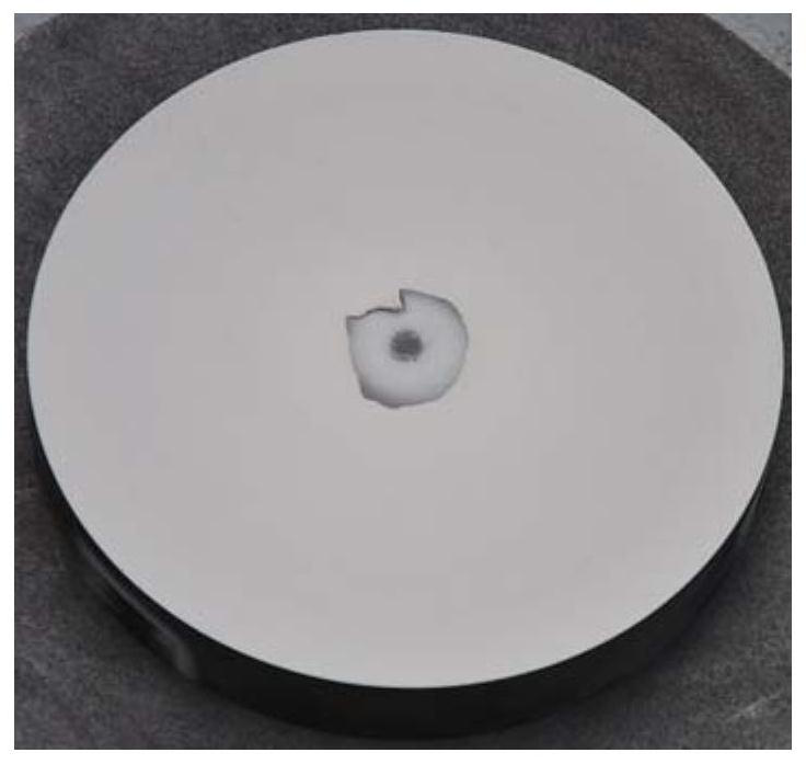
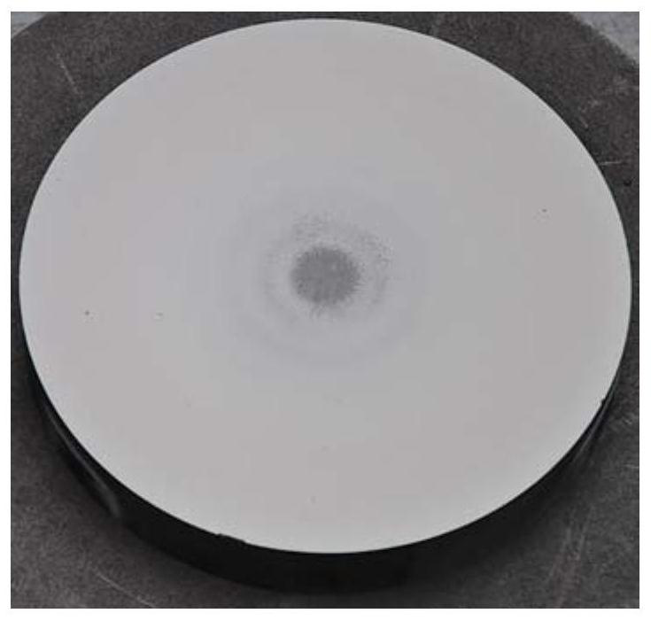
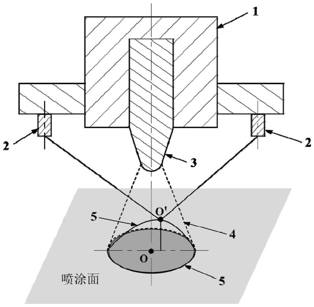
[0036] Existing spraying method is, the intersection point (as image 3 The O point in) is used as the position basis of spraying programming, and programming is carried out according to this method; The coating sprayed on the circular workpiece surface of the rotary body after the driver program is unclear due to the position of the center point of the actual spraying particle beam spot coating. The center point of the actual sprayed particle beam spot coating may have reached or exceeded the cen...


PUM


Abstract

The invention discloses an optical positioning method for the central point of a sprayed particle beam spot, which belongs to the technical field of surface engineering. The method is provided with several lasers on a spray gun, and the sprayed particle beam spot can be obtained conveniently and accurately through the focus points of the laser beam spots of several lasers. The position of the real center point can obtain the trajectory of the actual spraying particle beam spot on the surface of the target workpiece. The invention can conveniently and accurately carry out visual programming on the spraying trajectory, and the expected spraying trajectory after programming is consistent with the actual spraying trajectory; it can also be programmed conveniently and accurately for workpieces whose spraying size is unknown, whose size is difficult to measure or whose shape is complex; the spraying movement The trajectory is visualized throughout the process, which is convenient for verifying the spraying procedure.

Description

technical field [0001] The invention relates to the technical field of surface engineering, in particular to an optical positioning method for the center point of a spray particle beam spot. Background technique [0002] The spraying manipulator is used to spray plasma, flame, etc. on workpieces (especially workpieces with complex shapes). The prerequisite is to obtain the real center point of the sprayed particle beam spot, so as to obtain a visualized real spraying trajectory. This is the sprayed surface. One of the difficulties in the field of engineering technology. [0003] The current spraying method is to set the intersection of the nozzle center line and the surface of the sprayed workpiece ( image 3 Point O in ) is assumed to be the center point of the spraying particle beam spot, which is used as the position basis for spraying programming, and the trajectory of the spray gun is regarded as the spraying trajectory of the spraying particle beam spot. The problems ...

Claims


Application Information

Patent Timeline
Patent Type & Authority Patents(China)
IPC IPC(8): C23C4/129C23C4/134C23C4/11C23C4/18
CPCC23C4/18C23C4/11C23C4/129C23C4/134
Inventor 肖云锋汪敏王震宏王述钢税毅王嘉勇
Owner MATERIAL INST OF CHINA ACADEMY OF ENG PHYSICS
Why Eureka
Try Eureka