Combined cable bridge

A cable tray and combined technology, applied in electrical components and other directions, can solve problems such as large space occupation, and achieve the effects of improving applicability, reducing the number of parts, and having a simple structure

Pending Publication Date: 2019-12-20
江苏万有电气科技有限公司
View PDF0 Cites 3 Cited by
  • Summary
  • Abstract
  • Description
  • Claims
  • Application Information

AI Technical Summary

Problems solved by technology

[0004] The purpose of the present invention is to provide a combined cable tray to solve the problem of large space occupation when laying different cables in the prior art

Method used


Image

  • Combined cable bridge
  • Combined cable bridge
  • Combined cable bridge

Examples


Embodiment Construction

[0028] In order to make the technical means, creative features, goals and effects achieved by the present invention easy to understand, the present invention will be further described below in conjunction with specific embodiments.

[0029] It should be noted that, in the description of the present invention, the terms "front", "rear", "left", "right", "upper", "lower", "inner", "outer" and the like indicate orientations or positions The relationship is based on the orientation or positional relationship shown in the drawings, and is only for the convenience of describing the present invention and does not require that the present invention must be constructed and operated in a specific orientation, and thus should not be construed as a limitation of the present invention. The terms "front", "rear", "left", "right", "upper" and "lower" used in the description of the present invention refer to the directions in the drawings, and the terms "inner" and "outer" refer to is the dir...


PUM


Abstract

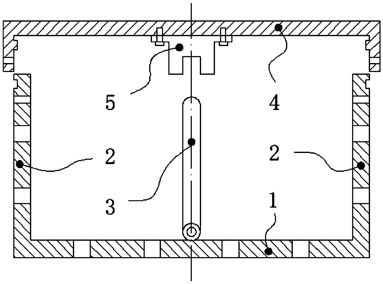
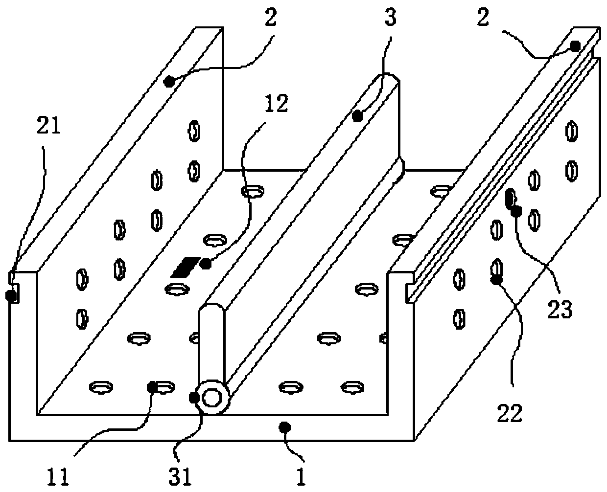
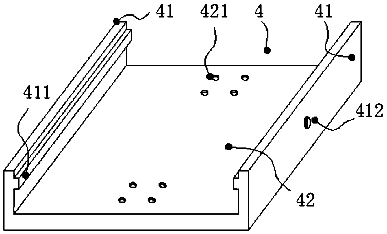
The invention discloses a combined cable bridge, which includes a cable box and a cover plate, wherein the cover plate is detachably connected to the cable box; a separating plate is arranged inside the cable box along a cable laying direction, and is rotatably connected to a first bottom plate of the cable box so as to have a unfolding position and at least one folding position in the cable box;in the unfolding position, the separating plate is vertically arranged on the first bottom plate to separate the internal space of the cable box; in the folding position, the separating plate is attached to the first bottom plate; the bottom surface of the cover plate is detachably connected with a fixing device; and the fixing device is configured to fix the separating plate in the unfolding position. The combined cable bridge can fix various cables by designing the separating plates having different positions.

Description

technical field [0001] The invention relates to the technical field of cable bridges, in particular to a combined cable bridge. Background technique [0002] Cable trays are divided into trough type, tray type, ladder type, grid type and other structures, and are composed of brackets, supporting arms and installation accessories. The bridge frame in the building can be erected independently or attached to various buildings and pipe gallery supports. It should reflect the characteristics of simple structure, beautiful appearance, flexible configuration and convenient maintenance. All parts need to be galvanized and installed in the building. An open-air bridge. [0003] When the cable trays in the prior art carry different types of cables, in order to avoid mutual interference between different cables, different cable trays are usually arranged separately to solve the above problems, but this way of arranging cable trays is time-consuming and laborious and requires occupatio...

Claims


Application Information

Patent Timeline
Patent Type & Authority Applications(China)
IPC IPC(8): H02G3/04
CPCH02G3/0481
Inventor 陈菊芳
Owner 江苏万有电气科技有限公司
Why Eureka
Try Eureka