Bidirectional or multidirectional DC-DC conversion circuit based on Royer

A technology for converting circuits and circuits, which is applied in the direction of output power conversion devices, electrical components, adjusting electrical variables, etc., to achieve the effect of avoiding control methods and small size

Pending Publication Date: 2019-12-20
胡江
View PDF5 Cites 0 Cited by
  • Summary
  • Abstract
  • Description
  • Claims
  • Application Information

AI Technical Summary

Problems solved by technology

Usually in use, the DC source is converted from the input end to the output end, and after passing through the transformer, the output end outputs a voltage corresponding to the turn ratio. The circuit can only input at the fixed end and output at the fixed end.

Method used


Image

  • Bidirectional or multidirectional DC-DC conversion circuit based on Royer
  • Bidirectional or multidirectional DC-DC conversion circuit based on Royer
  • Bidirectional or multidirectional DC-DC conversion circuit based on Royer

Examples


Embodiment Construction

[0013] The accompanying drawings are for illustrative purposes only and cannot be construed as limiting the patent;

[0014] In order to better illustrate this embodiment, some parts in the drawings will be omitted, enlarged or reduced, and do not represent the size of the actual product;

[0015] For those skilled in the art, it is understandable that some well-known structures and descriptions thereof may be omitted in the drawings;

[0016] Below in conjunction with accompanying drawing and embodiment the technical scheme of the present invention is described further;

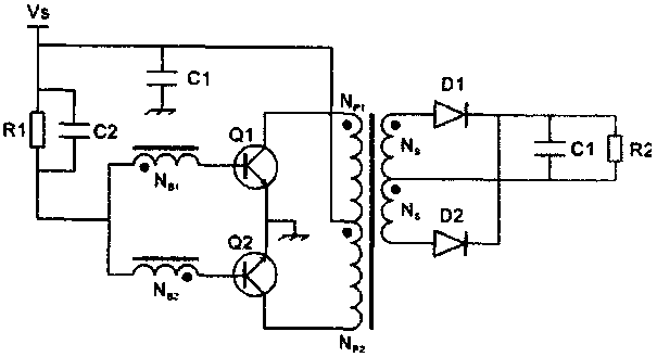
[0017] Such as figure 1 As shown, this circuit is a typical ROYER circuit diagram commonly used at present. Q1 and Q2 are turned on alternately; D1 and D2 are alternately rectified; electric energy is converted from VS to load R2;

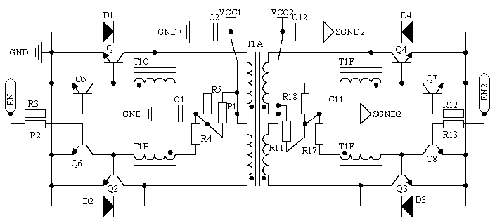
[0018] Such as figure 2 As shown, the first self-excited push-pull circuit composed of Q1, Q2, T1A, T1B, T1C, R1, and C1, when the EN1 pin is selected to be low, the first s...


PUM


Abstract

The invention relates to a bidirectional or multidirectional DC-DC conversion circuit based on a Royer circuit, which belongs to the technical field of switching power supplies. The circuit is characterized in that two or more than two self-excited push-pull circuits are subjected to magnetic circuit integration, and meanwhile, the self-excited push-pull circuits are compatible with a rectifying circuit, so that a bidirectional or multidirectional DC-DC electric energy conversion function is formed. The circuit is simple and flexible, and can be applied to energy exchange between batteries orbridging between sources when a DC source is separated for power supply. According to the bidirectional or multidirectional DC-DC conversion circuit provided by the invention, mutual electric energy conversion between two or more DCs is realized by utilizing corresponding magnetic integration or series-parallel connection among a plurality of conversions, functions are realized only by using a simple control mode and a smaller volume, and a complex control mode and higher cost are avoided.

Description

technical field [0001] The present invention relates to the field of power supplies, more specifically, to a Roye circuit-based bidirectional or multidirectional DC-DC conversion circuit for a DC-DC conversion power supply. Background technique [0002] The existing self-excited push-pull circuit, the circuit structure comes from the self-excited oscillating push-pull transistor single-transformer DC converter invented by G. H. Royer in 1955, which is also the beginning of realizing high-frequency conversion control circuit; part of the circuit comes from In 1957, the self-excited push-pull dual-transformer circuit invented by Jen Sen in the United States (Jen Sen in some places) was later called the self-oscillating soup Jensen circuit; these two circuits were collectively referred to as self-excited push-pull pull converter. The self-excited push-pull converter is described on pages 67 to 70 of "The Principle and Design of Switching Power Supply" published by Electronics ...

Claims


Application Information

Patent Timeline
Patent Type & Authority Applications(China)
IPC IPC(8): H02M3/335
CPCH02M3/33584
Inventor 胡江
Owner 胡江
Why Eureka
Try Eureka