Fixing fixture for synchronous cutting of multiple rectangular steel pipes

A technology for synchronous cutting and rectangular steel pipes, applied in the direction of clamping, positioning devices, clamping devices, etc., can solve problems such as deformation and bending of rectangular steel pipes, increase labor intensity of workers, and deformation of rectangular steel pipes, so as to reduce the range of horizontal movement and avoid Cantilever beam cutting, the effect of reducing the chance of deformation

Active Publication Date: 2019-12-24
福建泉州业德弗科技有限公司
View PDF13 Cites 5 Cited by
  • Summary
  • Abstract
  • Description
  • Claims
  • Application Information

AI Technical Summary

Problems solved by technology

[0007] The present invention can solve the problem of the existing fixing jig for cutting rectangular steel pipes. Usually, only one end of the rectangular steel pipe is fixed with a jig without other fixing tools, forming a cantilever beam cutting, which is easy to cause deformation of the cutting part of the rectangular steel pipe, and even the entire rectangular steel pipe. The phenomenon of deformation and bending. At the same time, during the cutting process of the middle part of the rectangular steel pipe, the two ends of the rectangular steel pipe will be tilted upwards, and the center will be shifted toward the cutting position. The cutting knife is prone to jamming, and the cutting section is uneven. It is easy to bend and deform. Cutting a rectangular steel pipe at a time has low work efficiency and low benefits, and it is easy to increase the labor intensity of workers. Usually, rigid clamps are used to clamp and fix it, which may easily cause cracks on the clamped parts of the rectangular steel pipe. Deformation and other problems

Method used


Image

  • Fixing fixture for synchronous cutting of multiple rectangular steel pipes
  • Fixing fixture for synchronous cutting of multiple rectangular steel pipes
  • Fixing fixture for synchronous cutting of multiple rectangular steel pipes

Examples


Embodiment Construction

[0029] The embodiments of the present invention will be described in detail below with reference to the accompanying drawings, but the present invention can be implemented in many different ways as defined and covered by the claims.

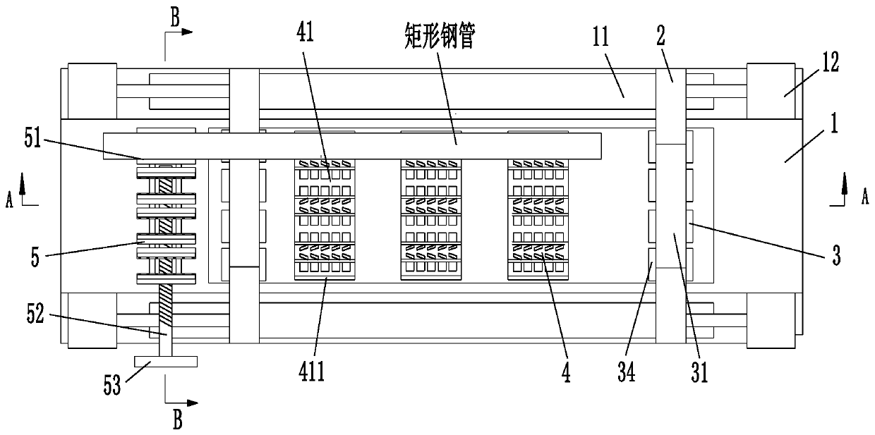
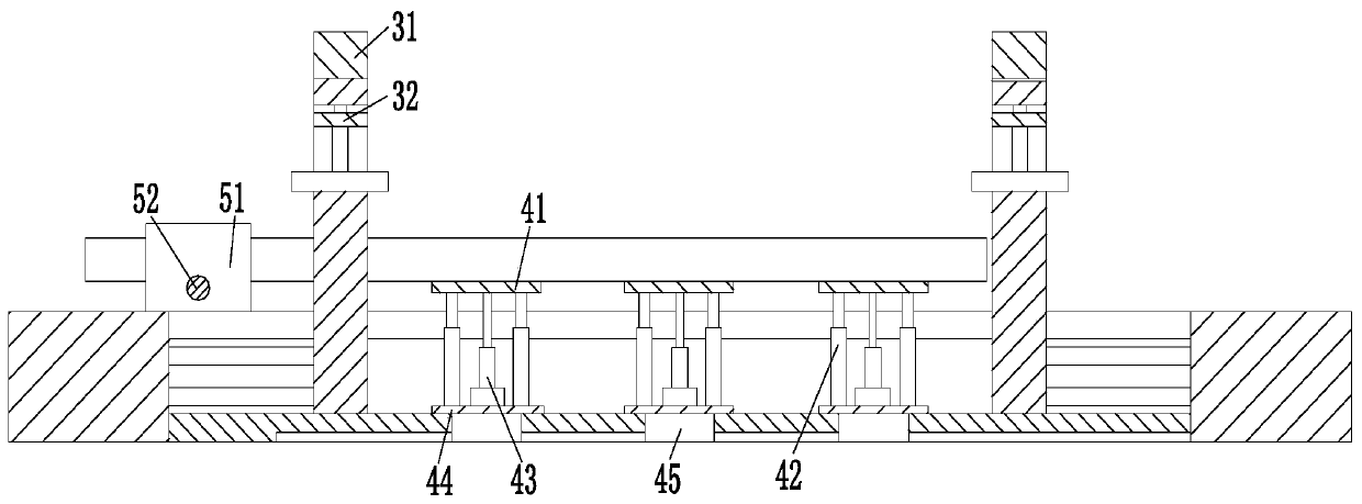
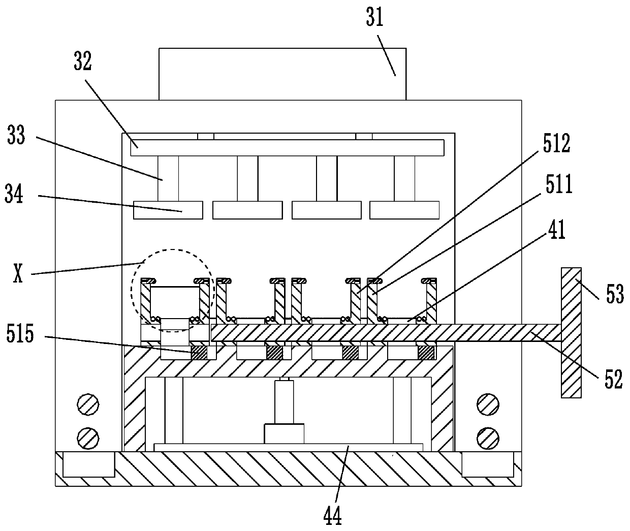
[0030] Such as Figure 1 to Figure 4 As shown, a fixed fixture for synchronous cutting of a plurality of rectangular steel pipes includes a workbench 1, a gantry frame 2, a pressing device 3, a supporting device 4 and a clamping device 5, and the left and right sides of the workbench 1 pass through The gantry 2 is symmetrically arranged in sliding mode, and the gantry 2 is provided with a pressing device 3 by sliding. The middle part of the workbench 1 is provided with a rectangular slot, and the supporting device 4 is arranged in the rectangular slot from left to right. A clamping device 5 is provided on the left side of the upper end surface of the workbench 1 , and the clamping device 5 is located on the left side of the gantry 2 on the left s...


PUM


Abstract

The invention relates to a fixing fixture for synchronous cutting of multiple rectangular steel pipes. The fixing fixture comprises a worktable, portal frames, pressing devices, supporting devices anda clamping device; the portal frames are symmetrically arranged on the left and right sides of the worktable through a sliding mode; the pressing devices are arranged on the portal frames through a sliding mode; a rectangular through groove is formed in the middle part of the worktable; the supporting devices are arranged in the rectangular through groove in sequence from left to right; and the clamping device is arranged on the left side of the upper end surface of the worktable, and is positioned on the left side of the portal frame on the left side of the worktable. The fixing fixture cansolve such difficulties as easy deformation of cutting places of the rectangular steel pipes or even bending deformation of the whole rectangular steel pipes due to cantilever beam type cutting formedby fixation of one ends of the rectangular steel pipes by using a fixture without needing other fixing tools, easy blockage of cutters and different cutting sections in a traditional fixing fixture for rectangular steel pipe cutting.

Description

technical field [0001] The invention relates to the field of steel pipe cutting jigs, in particular to a fixed jig for synchronously cutting multiple rectangular steel pipes. Background technique [0002] Fixture refers to the device used to fix or install the processing object in the process of mechanical manufacturing so that it can occupy the correct position to accept construction or inspection. It is also called fixture. The fixture has great versatility, high degree of standardization and quick operation. Safety and other features, the special fixture has the characteristics of specific service objects and strong pertinence. Nowadays, when cutting rectangular steel pipes, the fixture is usually used to fix the rectangular steel pipe first, and then the single rectangular steel pipe is processed, but during the cutting process. The following problem occurs: [0003] 1. Usually, only one end of the rectangular steel pipe is fixed with a clamp, without other fixing tools...

Claims


Application Information

Patent Timeline
Patent Type & Authority Applications(China)
IPC IPC(8): B23Q3/08B23Q11/00
CPCB23Q3/061B23Q3/064B23Q3/08B23Q11/0032B23Q2703/04
Inventor 林明辉
Owner 福建泉州业德弗科技有限公司
Why Eureka
Try Eureka