Engine auxiliary starter

An engine and starter technology, applied in the direction of engine starting, engine components, machines/engines, etc., can solve problems such as short service life, achieve the effect of high combination success rate, ensure stable start, and eliminate stagnation period

Pending Publication Date: 2019-12-24
台州擎农机械有限公司
View PDF5 Cites 7 Cited by
  • Summary
  • Abstract
  • Description
  • Claims
  • Application Information

AI Technical Summary

Problems solved by technology

[0006] The purpose of the present invention is to address the above-mentioned problems in the prior art,

Method used


Image

  • Engine auxiliary starter
  • Engine auxiliary starter
  • Engine auxiliary starter

Examples


Embodiment 1

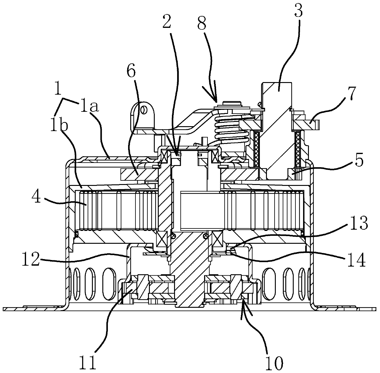
[0045] Such as figure 1 As shown, the auxiliary starter of the engine includes a body 1, a rotatable shaft 2 provided on the body 1 and capable of driving the shaft 2 to rotate, and a clutch mechanism connected to the shaft 2.

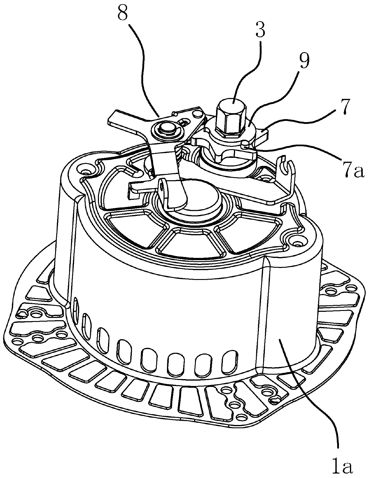
[0046] Such as figure 1 with figure 2 As shown, the body 1 includes a casing 1a with one end open and the other end closed, and a spring box 1b fixed in the casing 1a. The spring box 1b is provided with a spiral spring 4, and one end of the outer edge of the spiral spring 4 is fixed to the spring. On the box 1b, the rotating shaft 2 passes through the center of the scroll spring 4, and one end of the inner edge of the scroll spring 4 is connected to the rotating shaft 2. One end of the starting shaft 3 is located in the housing 1 a and is connected with a driving gear 5, one end of the rotating shaft 2 extends out of the spring box 1 b and is connected with a driven gear 6, and the driving gear 5 meshes with the driven gear 6. A ratchet 7 is sleeved on o...

Embodiment 2

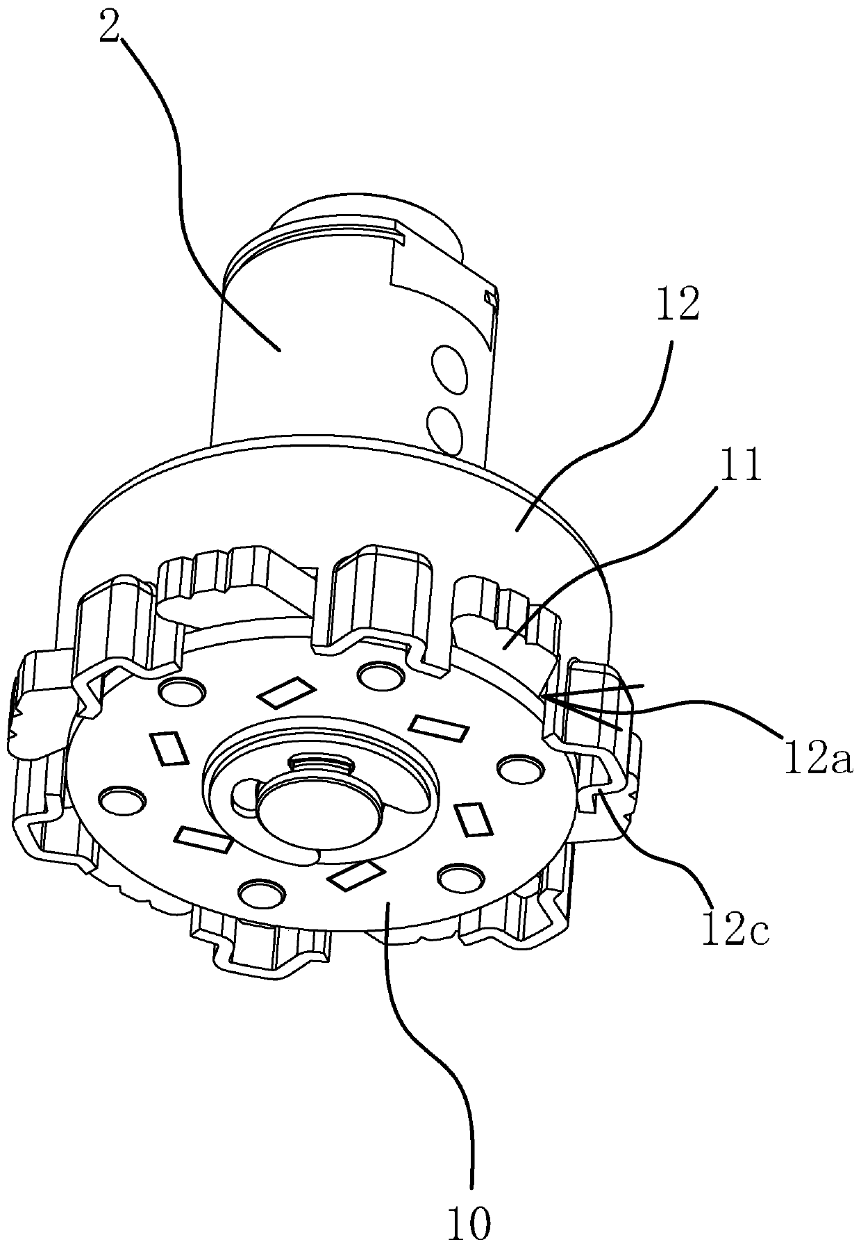
[0056] The structure and principle of this embodiment are basically the same as those of the first embodiment, but the difference lies in: Figure 8-10 As shown, in this embodiment, the number of activation claws 11 is three, and the outer edge of the claw base 10 is provided with a number of accommodating grooves 10a3, each activation claw 11 is located in each accommodating groove 10a3, and the limiting portion 10a1 is the accommodating groove The inside of 10a3 corresponds to the side wall in the center direction of the claw base 10. Specifically, the claw seat 10 includes an upper seat body 10a and a lower seat body 10b. The receiving groove 10a3 is opened between the lower end surface and the outer peripheral surface of the upper seat body 10a. The lower seat body 10b limits the activation pawls 11 in the receiving groove 10a3 to prevent Prolapse. The limiting portion 10a1 is an outer convex arc surface, and the inner end of the activation pawl 11 is provided with an inne...


PUM


Abstract

The invention provides an engine auxiliary starter, belongs to the technical field of machinery, and solves the problem of short service life of a traditional auxiliary starter. The engine auxiliary starter comprises a rotating shaft, a jaw base peripherally fixed on the rotating shaft, and a friction piece capable of generating the rotating resistance for the jaw base; the jaw base is hinged withmultiple starting jaws distributed around the rotating shaft and capable of swinging relative to the jaw base; multiple jaw outlets are arranged at the side part of the friction piece in the peripheral direction; the outer ends of all the starting jaws are positioned in the corresponding jaw outlets; the friction piece is provided with starting grooves between two adjacent jaw outlets; starting parts positioned in the starting grooves are projected at the inner ends of the starting jaws in the radial directions; and the rotating shaft can be rotated to enable the starting parts to abut against the walls of the starting grooves. The engine auxiliary starter has such advantages as long service life, short opening time of the starting jaws and high success rate of combination with starting cups.

Description

Technical field [0001] The invention belongs to the field of auxiliary starting equipment and relates to an auxiliary starter of an engine. Background technique [0002] With the continuous economic development, the degree of agricultural mechanization is getting higher and higher, and agricultural farming equipment is more and more commonly used. Its power source is basically an air-cooled diesel engine, which must be assisted before work Start the device to enter the running state. The commonly used auxiliary starting equipment on the market also adopts the manual starting mode of transmission. It is used by the driver to use the crank to drive the starting mechanism on the auxiliary starting device to start, and the starting mechanism is used to drive the shaft to rotate to turn the auxiliary starting device. The inner scroll spring tightens the elastic force, and then generates explosive force when the elastic force of the scroll spring is released to drive the starter cup o...

Claims


Application Information

Patent Timeline
IPC IPC(8): F02N5/02F02N15/02
CPCF02N5/02F02N15/02
Inventor 何洪伟林勇
Owner 台州擎农机械有限公司
Why Eureka
Try Eureka