
Threading mechanism for automatic winding machine

An automatic winding machine and threading technology, which is applied in coil manufacturing and other directions, can solve problems such as low threading efficiency

Pending Publication Date: 2019-12-24
东电化电子(珠海)有限公司
View PDF0 Cites 0 Cited by
  • Summary
  • Abstract
  • Description
  • Claims
  • Application Information

AI Technical Summary

Problems solved by technology

However, when making magnetic ring inductors, the copper wire is usually manually passed through the magnetic ring and then the copper wire is wound. Manual threading results in low threading efficiency

Method used


Image

  • Threading mechanism for automatic winding machine
  • Threading mechanism for automatic winding machine
  • Threading mechanism for automatic winding machine

Examples


Embodiment Construction

[0020] In order to make the object, technical solution and advantages of the present invention clearer, the present invention will be further described in detail below in conjunction with the accompanying drawings and embodiments. It should be understood that the specific embodiments described here are only used to explain the present invention, not to limit the present invention.

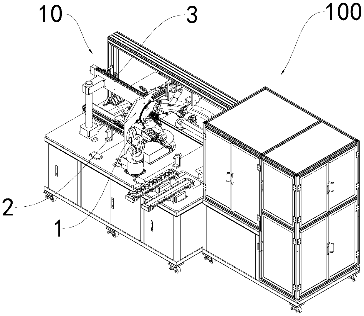
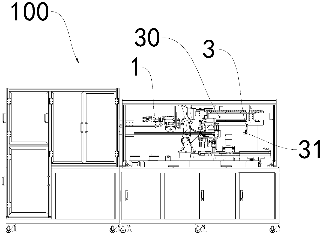
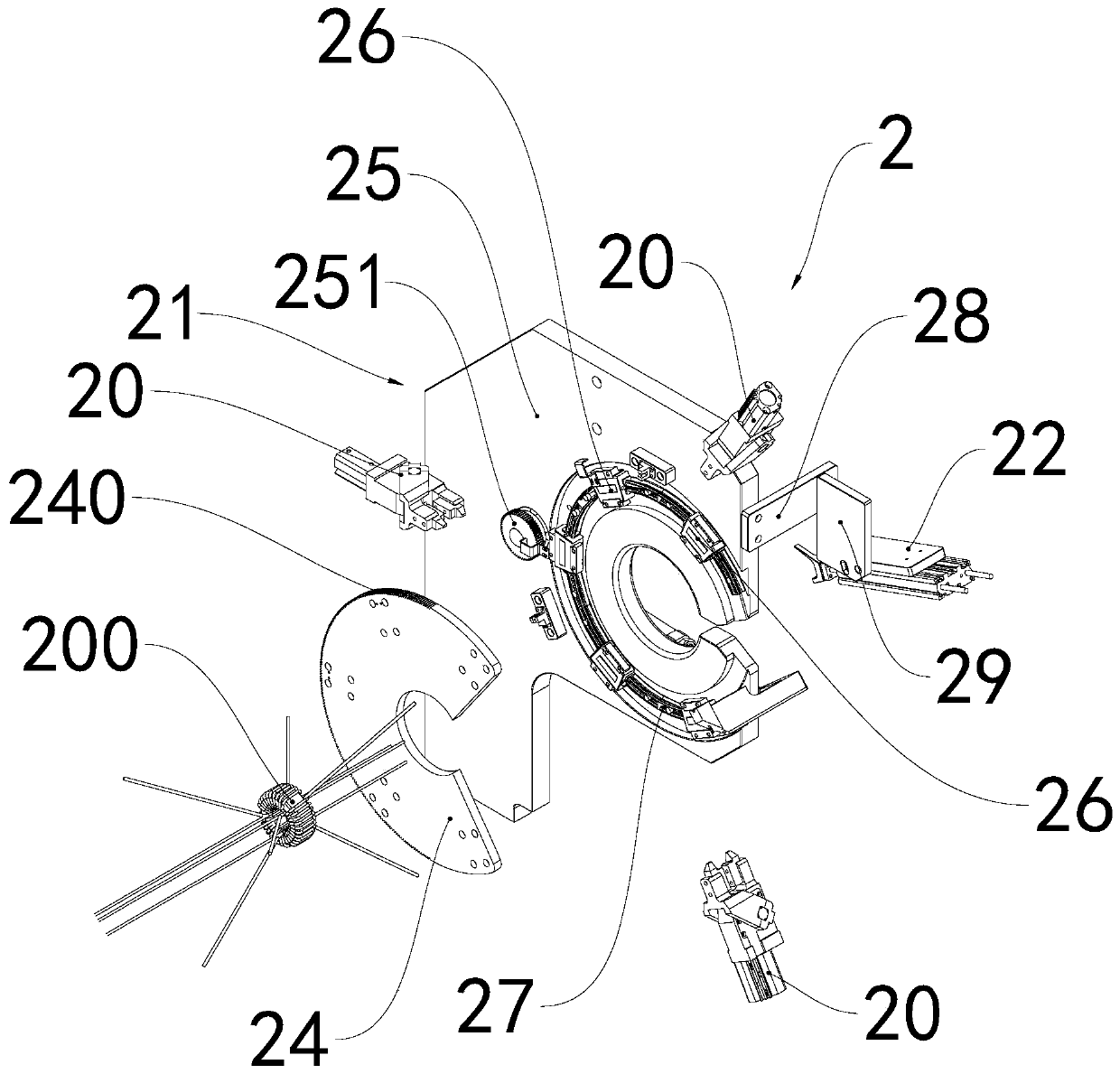
[0021] see figure 1 and figure 2 , the threading mechanism 10 for the automatic winding machine 100 includes a thread taking device 1, a fixing device 2 and a thread setting device 3, the thread taking device 1 and the thread setting device 3 are arranged on both sides of the fixing device 2, and the thread setting device 3 includes The guide rail 30 and the alignment clip 31 , the guide rail 30 is assembled on the fixing device 2 , and the alignment clip 31 is movably assembled on the guide rail 30 . The thread taking device 1 is a six-axis manipulator, and the thread taking device is provided ...


PUM


Abstract

The invention relates to a threading mechanism for an automatic winding machine. The threading mechanism comprises a wire taking device, a fixing device and a wire fixing device. The wire taking device and the wire fixing device are arranged on the two sides of the fixing device respectively. The wire fixing device comprises a guide rail and a wire fixing clamp, the guide rail is assembled on thefixing device, and the wire fixing clamp is movably assembled on the guide rail. The fixing device comprises a clamping jaw, a base part, a shaping device and a driving device, the clamping jaw is movably assembled on the base part, the shaping device is connected to the base part, the wire taking device and the clamping jaw are arranged on the same side of the base part, the wire fixing device and the shaping device are arranged on the same side of the base part, and the driving device penetrates through the base part. The wire taking device clamps a copper wire to the fixing device, the wirefixing clamp of the wire fixing device can clamp the copper wire, the wire fixing clamp moves along the guide rail to enable the copper wire to penetrate through the fixing device, and the automaticwire threading is achieved.

Description

technical field [0001] The invention belongs to the technical field of winding, and in particular relates to a threading mechanism for an automatic winding machine. Background technique [0002] At present, magnetic ring inductors are one of the most commonly used equipment in the fields of electricity and automation. Magnetic ring inductors are made by winding copper wires on magnetic rings. However, when manufacturing magnetic ring inductors, copper wires are usually wound through the magnetic ring manually, and the manual threading results in low threading efficiency. Contents of the invention [0003] The main purpose of the present invention is to provide a threading mechanism for an automatic winding machine that realizes automatic threading. [0004] In order to achieve the above-mentioned main purpose, the threading mechanism for the automatic winding machine provided by the present invention includes a thread taking device, a fixing device and a thread setting de...

Claims


Application Information

Patent Timeline
IPC IPC(8): H01F41/08
CPCH01F41/08
Inventor 李生李嘉杰钟富林
Owner 东电化电子(珠海)有限公司
Learn More