
Beverage machine

A beverage machine and beverage technology, which is applied to beverage preparation devices, household appliances, applications, etc., can solve the problems of high volume of coffee machines, few of them, and long production time.

Inactive Publication Date: 2019-12-27
GUANGDONG MIDEA CONSUMER ELECTRICS MFG CO LTD
View PDF11 Cites 1 Cited by
  • Summary
  • Abstract
  • Description
  • Claims
  • Application Information

AI Technical Summary

Problems solved by technology

In most of the coffee machines currently on the market, the brewing system is located on the upper part of the coffee machine. Due to the influence of the coffee cup and the brewing system, the coffee machine with this layout is relatively tall, which not only takes up space in the kitchen, but also takes up a lot of space when moving. inconvenient
[0003] In addition, most of the current coffee machines can only make hot drinks or cold drinks, and few have both.
When the coffee machine is brewing cold coffee, the extraction effect is not good, and the extraction time is very long. This is because the density of most ingredients is lower than that of water. It is difficult for the extract to be fully soaked. For example, it is difficult to fully extract the extract in cold water without pressure, so not only the extraction time is very long, but also the extraction is not sufficient, resulting in a low concentration of the solution;
[0004] In addition, if you want to obtain high-quality extract, you need to have a very good filtering effect, so the pores of the filter are very small, so that the small particles of the extract can easily seal the filter, so the extract is difficult to seep out , which is one of the main reasons for the long production time

Method used


Image

  • Beverage machine
  • Beverage machine
  • Beverage machine

Examples


Embodiment Construction

[0030] Specific embodiments of the present invention will be described in detail below in conjunction with the accompanying drawings. It should be understood that the specific embodiments described here are only used to illustrate and explain the present invention, and are not intended to limit the present invention.

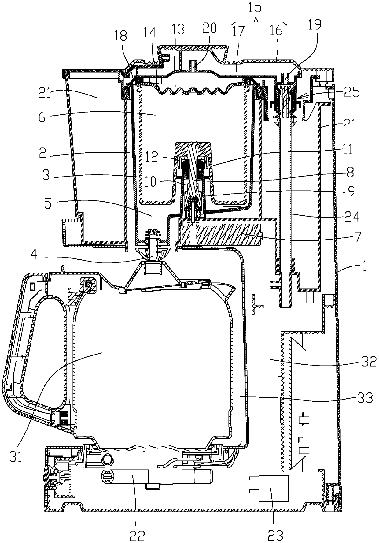
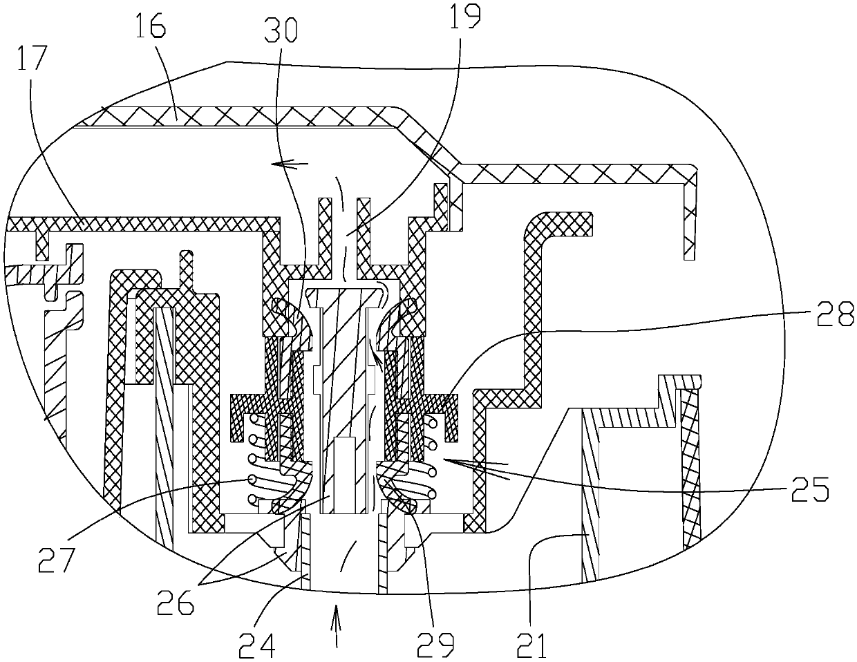
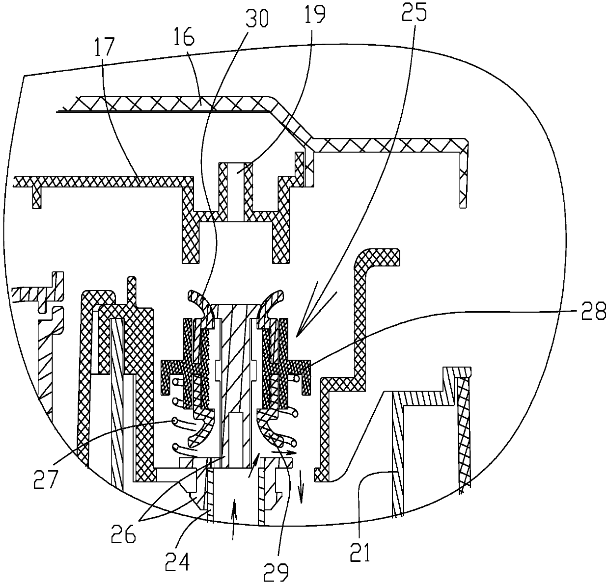
[0031] refer to figure 1 With the shown structure, the beverage machine 32 provided by the present invention includes a seat housing 1, a beverage funnel 2 and a beverage filter screen 3, wherein the beverage funnel 2 can be lapped on the seat housing in any suitable manner such as the edge of the beverage funnel 2 turned outward. The four sides of the containing space of the body 1 are fixedly arranged on the seat housing 1, and the drink funnel 2 includes a drink containing cavity 5 having a drink spout 4, so that the drink in the drink containing cavity 5 will flow out through the drink spout 4, and Beverage strainer 3 comprises beverage brewing chamber 6 an...


PUM


Abstract

The invention relates to the technical field of beverage brewing, and discloses a beverage machine. The beverage machine comprises a base shell, a beverage funnel and a beverage filter screen, the beverage funnel is fixedly arranged on the base shell and comprises a beverage containing cavity with a beverage leaking opening, and the beverage filter screen comprises a beverage brewing cavity and can be rotationally arranged in the beverage funnel. During thermal extraction, beverage raw materials and hot water are put into the beverage brewing cavity, the hot water can fully brew the beverage raw materials, if needed, the beverage filter screen can be rotated, the soaking effect of the hot water and the beverage raw materials can be improved, and after thermal extraction is completed, the beverage filter screen can be rotated to spin-dry beverage raw material residues, so that cleaning is convenient; during cold extraction, cold water and beverage raw materials are put into the beveragebrewing cavity, the beverage filter screen is rotated at the moment, and the cold water and the beverage raw materials are driven to rotate under the action of rotating force, so that the cold waterand the beverage raw materials are fully mixed and soaked, the cold extraction effect of the beverage is improved, and the cold extraction time is correspondingly shortened.

Description

technical field [0001] The invention relates to the technical field of beverage brewing, in particular to a beverage machine. Background technique [0002] With the improvement of the quality of life, more and more people like to drink coffee. In most of the coffee machines currently on the market, the brewing system is located on the upper part of the coffee machine. Due to the influence of the coffee cup and the brewing system, the coffee machine with this layout is relatively tall, which not only takes up space in the kitchen, but also takes up a lot of space when moving. inconvenient. [0003] In addition, most of the current coffee machines can only make hot drinks or cold drinks, and rarely both. When the coffee machine brews cold coffee, the extraction effect is not good, and the extraction time is very long. This is because the density of most ingredients is lower than that of water. It is difficult for the extract to be fully soaked. For example, it is difficult ...

Claims


Application Information

Patent Timeline
IPC IPC(8): A47J31/44A47J31/46A47J31/10
CPCA47J31/10A47J31/4403A47J31/462
Inventor 朱国军
Owner GUANGDONG MIDEA CONSUMER ELECTRICS MFG CO LTD
Learn More