
Four-way adjustment steering column assembly

A technology for steering column assembly and column, which is applied in steering control, steering mechanism, transportation and packaging, etc., can solve the problems of noise performance, high cost, low production capacity, etc., so as to increase enterprise production capacity, reduce enterprise cost, increase The effect of competitiveness

Inactive Publication Date: 2019-12-27
지엠프리시젼인더스트리오토모티브콤포넨츠(쑤저우)캄퍼니리미티드
View PDF8 Cites 0 Cited by
  • Summary
  • Abstract
  • Description
  • Claims
  • Application Information

AI Technical Summary

Problems solved by technology

[0003] At present, in the automobile industry, the traditional four-way adjustment steering column uses aluminum casting upper tube as the main part in order to reduce the friction noise of iron parts and meet the performance requirements. However, this style has high cost and low production capacity. It is basically used in On high-end models; the traditional four-way adjustment column, the lower tube is made of iron, and the upper tube is made of aluminum, so the friction between the upper and lower tubes will produce a lot of aluminum chips, which will cause noise and other performance effects; the traditional four-way adjustment column is To meet the sliding holding force, the aluminum tube is used to hug the iron pipe to collapse. Basically, the sliding force is the lower limit of the offset. If the sliding force is increased, the handle force will also be increased, which will exceed the upper limit.

Method used


Image

  • Four-way adjustment steering column assembly
  • Four-way adjustment steering column assembly
  • Four-way adjustment steering column assembly

Examples


Embodiment Construction

[0016] The present invention will be further described below in conjunction with accompanying drawing.

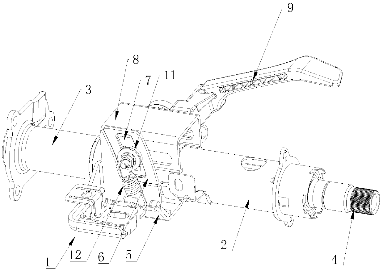
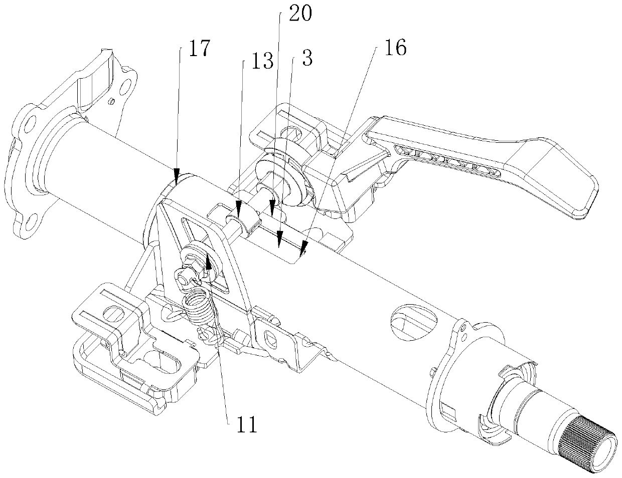
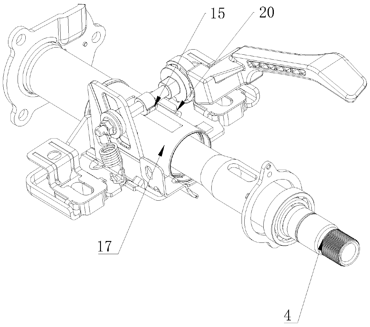
[0017] Such as figure 1 As shown, a four-way adjustable steering column assembly includes a bracket 1, an upper column 2, a lower column 3, and a steering shaft 4 arranged in the upper column 2 and the lower column 3, the upper column 2 and the lower column 3 are made of iron, the bracket 1 includes a support seat 5, a limit plate 6 is arranged on the support seat 5, and an adjustment hole 7 is arranged on the limit plate 6, and the limit plate 6 is connected with support sleeves 8 arranged on both sides of the outer wall of the upper column 2, and the side of the support sleeve 8 opposite to the limit plate 6 is provided with an adjustment handle 9, and the adjustment handle 9 is connected with a The adjustment shaft 10 in the cylinder 8 and the limit plate 6, the end of the adjustment shaft 10 is provided with an adjustment bolt 11 abutting against the limit plate 6, a s...


PUM


Abstract

The invention discloses a four-way adjustment steering column assembly. The technical scheme of the invention is that the four-way adjustment steering column assembly comprises a support, an upper tubular column, a lower tubular column and the steering shafts arranged in the upper tubular column and the lower tubular column. The upper tubular column and the lower tubular column are both made of iron, the support comprises a supporting base, and a limiting plate is arranged on the supporting seat; an adjusting hole is formed on the limiting plate, the limiting plate is connected with the supporting sleeves arranged at the two sides of the outer wall of the upper pipe column, and the adjusting handles are arranged at the sides, opposite to the limiting plate, of the supporting sleeves. The adjusting handles are connected with the adjusting shafts inserted into the supporting sleeves and the limiting plates, the adjusting bolts abutting against the limiting plate are arranged at the tailends of the adjusting shafts, and the springs are arranged between the adjusting shafts and the supporting base. A pressing block is arranged on each adjusting shaft, an annular part and a protrudingpart with the diameter larger than that of the annular part are arranged on the outer wall of the pressing block, and the pressing block penetrates through a through hole to directly abut against theouter wall of the lower tubular column. According to the scheme provided by the invention, the cost is low, and the sliding force can be adjusted on the basis of not influencing the handle force.

Description

technical field [0001] The invention relates to the technical field of automobile steering system components, in particular to a four-way adjustable steering column assembly. Background technique [0002] Automobile steering column components are one of the important components in the steering system. According to different adjustment methods, the steering column can be divided into non-adjustable column (fixed), two-way adjustable column (up and down direction adjustment), four-way adjustment Pipe string (up and down, front and rear direction adjustment). There are many ways to adjust the steering wheel and steering column, mainly to meet the comfort and safety requirements of the driver. Due to the different body shapes, each person has different requirements for the comfort of the steering wheel's driving adjustment position. Therefore, in general, the four One-way adjustment is better than two-way adjustment. [0003] At present, in the automotive industry, the traditi...

Claims


Application Information

Patent Timeline
Patent Type & Authority Applications(China)
IPC IPC(8): B62D1/187
CPCB62D1/187
Inventor 申凤哲
Owner 지엠프리시젼인더스트리오토모티브콤포넨츠(쑤저우)캄퍼니리미티드
Learn More