
Wire groove for knitting machine

A mechanical, wire trough technology, applied in knitting, weft knitting, warp knitting and other directions, can solve the problems of lack of elasticity, inability to cope with excessive tension and breakage, wire body grinding, etc., to avoid wire collapse. , reduce consumables, reduce the effect of fluffing

Active Publication Date: 2020-11-20
台州施特自动化有限公司
View PDF6 Cites 0 Cited by
  • Summary
  • Abstract
  • Description
  • Claims
  • Application Information

AI Technical Summary

Problems solved by technology

[0005] Aiming at the deficiencies of the prior art, the present invention provides a wire groove for knitting machines, which solves the problem that some existing wire grooves are easy to cause the thread body to be roughened when used, and do not have a certain elastic effect, so they cannot cope with The problem of excessive tension and breakage caused by equipment failure during the use of weaving thread

Method used


Image

  • Wire groove for knitting machine
  • Wire groove for knitting machine
  • Wire groove for knitting machine

Examples


Embodiment Construction

[0024] The following will clearly and completely describe the technical solutions in the embodiments of the present invention with reference to the accompanying drawings in the embodiments of the present invention. Obviously, the described embodiments are only some, not all, embodiments of the present invention. Based on the embodiments of the present invention, all other embodiments obtained by persons of ordinary skill in the art without making creative efforts belong to the protection scope of the present invention.

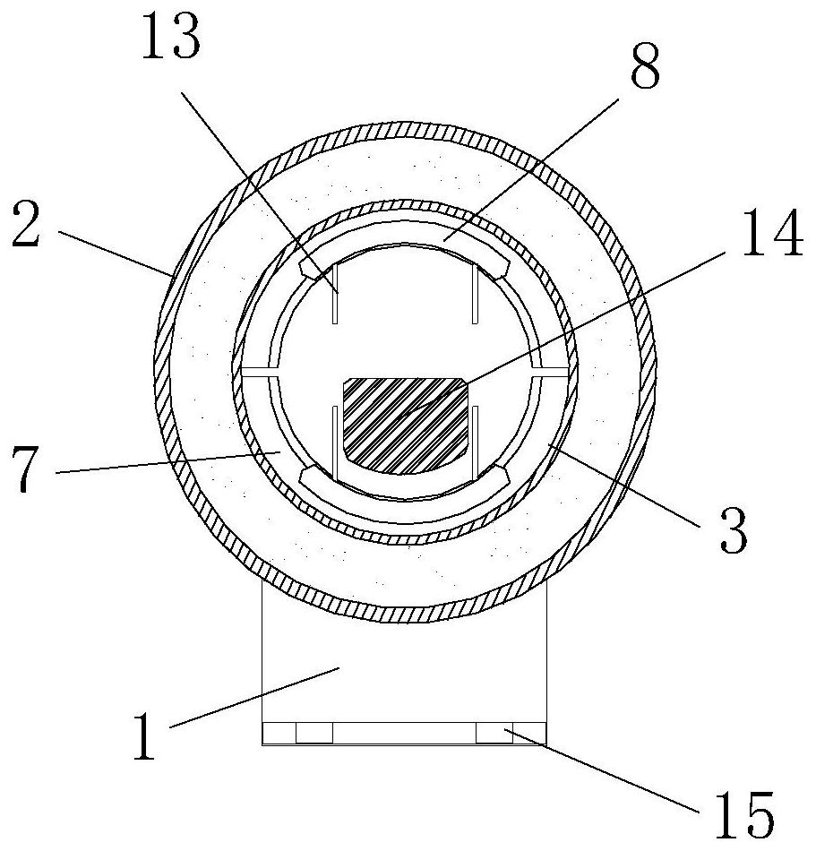
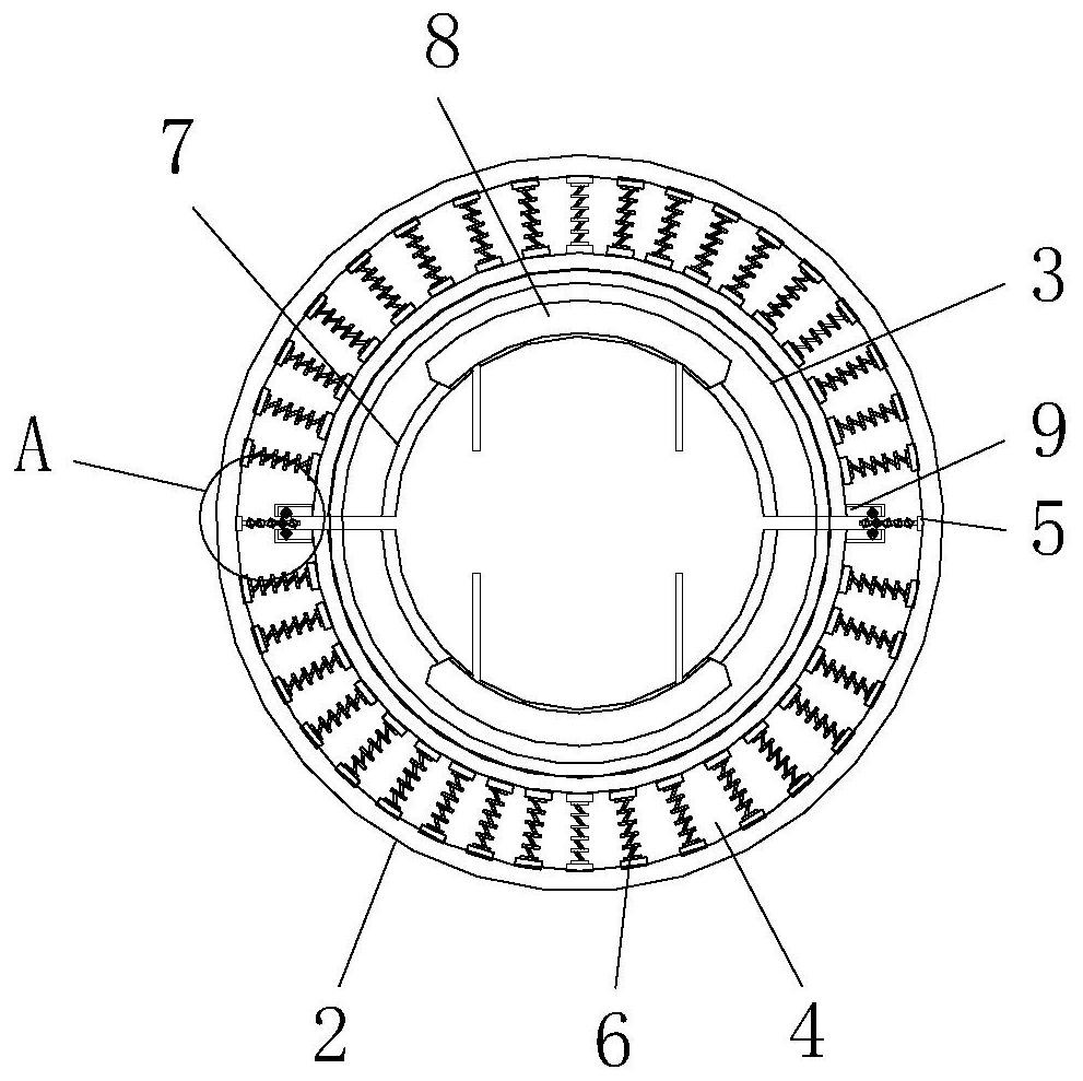
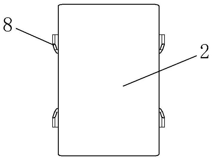
[0025] like Figure 1-5 As shown, the present invention provides a technical solution: a wire groove for knitting machinery, including a fixed rod 1, a wire member 2, a reserved groove 3, a cavity 4, a fixed block 5, a spring member 6, a movable block 7, a protective Sheet 8, connecting block 9, first gear 10, cross bar 11, second gear 12, limiter 13, knitting thread 14 and connecting hole 15, the upper end of fixed rod 1 is fixed with wire guide 2, and the in...


PUM


Abstract

The invention discloses a thread guide channel for knitting machinery, which comprises a fixing bar, a movable block and limiters. The upper end of the fixing bar is fixedly provided with a thread guide, and the inner surface of the thread guide is symmetrically provided with reserved grooves; a cavity is reserved in the thread guide, and fixing blocks are symmetrically welded on two side edges ofthe cavity; both the top and bottom of the cavity are provided with springs at equal intervals, and the movable block is mutually connected with the thread guide through the reserved grooves; the rear end surface of the movable block and the front end surfaces of the springs are mutually fixed; a protective sheet is fixed on the inner side surface of the movable block, and connecting blocks are fixed on two sides of the movable block; the fixing blocks are fixed at the front ends of cross bars, and second gears are fixed inside the cross bars at equal intervals; and the limiters are fixed onthe surface of the protective sheet. The U-shaped protective sheet fixed on the surface of the movable block of the thread guide channel for the knitting machine can ease the napping issue caused by large friction force in the conveying process of knitting threads.

Description

technical field [0001] The invention relates to the technical field of knitting, in particular to a wire groove for a knitting machine. Background technique [0002] Knitting refers to the process of using knitting needles to form coils of various raw materials and varieties of yarns, and then connect them into knitted fabrics through strings. The knitted fabrics are soft in texture, have good wrinkle resistance and air permeability, and have a large extension In addition to being used for clothing and decoration, knitted products can also be used in the fields of industry, agriculture, medical care and national defense. Knitting is divided into two categories: hand knitting and machine knitting. Hand knitting uses stick needles, which has a long history and exquisite craftsmanship. , the flower shape is flexible and changeable, and has been widely spread and developed among the people. [0003] Most of the existing knitting machines have wire devices fixed inside, but some...

Claims


Application Information

Patent Timeline
Patent Type & Authority Patents(China)
IPC IPC(8): D04B15/54D04B27/10
CPCD04B15/54D04B27/10
Inventor 彭珍
Owner 台州施特自动化有限公司
Learn More