AI technical title is built by Patsnap AI team. It summarizes the technical point description of the patent document.
An arch installation machine and clamping technology, which is applied to shaft equipment, shaft lining, mining equipment, etc., can solve the problems of reducing stroke efficiency, failing to operate strokes, and not considering energy consumption, flexibility, installation, and increased energy consumption. Achieve the effects of improving energy utilization and working power, saving materials and load weight, and increasing service life
Active Publication Date: 2020-10-09
RAILWAY NO 5 BUREAU GRP FIRST ENG CO LTD
View PDF9 Cites 0 Cited by
Summary
Abstract
Description
Claims
Application Information
AI Technical Summary
This helps you quickly interpret patents by identifying the three key elements:
Problems solved by technology
Method used
Benefits of technology
Problems solved by technology
[0004] 1. The arch installation machine of the prior art only considers the clamping problem of the clamping hand, but does not consider the clamping mechanics problem, and often causes fatigue stress damage after a long time of use, causing safety hazards
[0005] 2. In the arch installation machine of the prior art, the clamping hand uses a hydraulic cylinder to control the opening and closing, but the hydraulic cylinder is often external. Due to the angle of the external hydraulic cylinder, the component force of the clamping hand opening is small. Therefore, additional energy consumption is increased, and the external hydraulic cylinder increases the volume of the clamping hand; since the cylinder is straight and fixed on the clamping arm, the flexibility of the clamping arm is affected, so that the clamping arm cannot be flexibly bent
[0006] 3. The arch installation machine of the prior art only considers the functionality, but does not consider the problems of energy consumption, flexibility and installation
[0007] 4. The arch installation machine in the prior art often fixes the cables on the side of the hanging basket arm. However, this method is not suitable for the telescopic arm. The pipeline expands and contracts with the telescopic arm, and it is easy to cross the line.
[0008] 5. With the arch installation machine in the prior art, the hanging basket is lifted to the position and located on one side of the arch. If you think of the construction on the other side of the arch, you need to go in a "concave" shape, which greatly reduces the stroke efficiency and cannot be carried out on a high-precision scale. stroke operation
[0009] 6. The arch installation machine in the prior art has few degrees of freedom for the clamping module and the hanging basket module, and only realizes basic functions, and it is difficult to realize complex multi-degree-of-freedom actions through a simple structure; and the hanging basket is easy to tilt and unstable
Method used
Image
Click on the blue label to locate the original text in one second.
Reading with bidirectional positioning of images and text.
Examples
Embodiment Construction
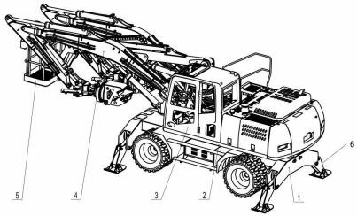
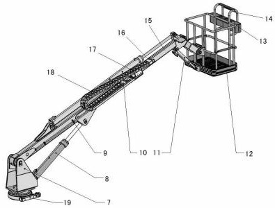
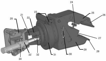
[0038] As shown in the figure: a stable clamping arch installation machine, including a storage frame, a chassis, a cockpit, a clamping arm, a basket assembly, a leg, a connecting frame, a hollow part, a swing arm, a hydraulic motor, and a limit Protrusion, upper splint, triangular block, shoulder, upper backing plate, lower backing plate, lower clamping block, clamping cylinder, slewing mechanism, cylindrical connection piece, swing arm cylinder, ring connection piece; the hanging basket assembly includes the support , Pitch cylinder, outer arm, telescopic cylinder, leveling cylinder, hanging basket, back body platform, escalator, inner arm, first joint, second joint, crawler belt, rotary drive mechanism;
[0039] As shown in the figure: the cockpit is provided above the underframe, a gondola assembly is provided in the middle of the front of the cockpit, a clamping arm is provided on both sides of the gondola assembly, and a clamping arm is provided at the front and rear of t...
PUM
Abstract
The invention relates to a stable clamping bow member assembling machine which comprises storage racks, a chassis, a driving cabin, clamping arms, a basket assembly, supporting legs, a connecting rack, a hollowed part, a swing arm, a hydraulic motor, a limiting bump, an upper clamping plate, a triangular block, a circular bead, an upper base plate, a lower base plate, a lower clamping block, a clamping oil cylinder, a rotating mechanism, a cylindrical connector, a swing arm oil cylinder and an annular connector. The basket assembly comprises a support, a pitch oil cylinder, an outer arm, a telescopic oil cylinder, a leveling oil cylinder, a basket, a back table, a ladder, an inner arm, a first joint, a second joint, a caterpillar band and a rotary driving mechanism. The driving cabin is arranged above the chassis, the basket assembly is arranged in the middle in front of the driving cabin, the calming arms are separately arranged on two sides of the basket assembly, the storage racks are separately arranged in front and behind the chassis, the supporting legs are arranged in the storage racks, and the supporting legs are supported on the ground when being unfolded and are stored inthe storage racks when being shrunk.
Description
technical field [0001] The invention relates to the field of tunnel construction, in particular to a stable clamping arch installation machine. Background technique [0002] In the construction process of domestic mine roadways, railway and highway tunnels, water conservancy culverts, various underground projects, high-rise building foundation pits, military projects, etc., arch support tunnels are required. At present, the installation of steel arches in domestic tunnel construction is still mainly done manually or with the help of other equipment, which not only has relatively high labor intensity, but also cannot guarantee efficiency and safety. In order to achieve high-efficiency mechanized construction, arch installation machines were initially used. [0003] However, in the actual use of the wet spraying machine, there are the following problems: [0004] 1. The arch installation machine of the prior art only considers the clamping problem of the clamping hand, but d...
Claims
Application Information
Patent Timeline
Application Date:The date an application was filed.
Publication Date:The date a patent or application was officially published.
First Publication Date:The earliest publication date of a patent with the same application number.
Issue Date:Publication date of the patent grant document.
PCT Entry Date:The Entry date of PCT National Phase.
Estimated Expiry Date:The statutory expiry date of a patent right according to the Patent Law, and it is the longest term of protection that the patent right can achieve without the termination of the patent right due to other reasons(Term extension factor has been taken into account ).
Invalid Date:Actual expiry date is based on effective date or publication date of legal transaction data of invalid patent.

