
A fault diagnosis device with an anti-magnetic field signal interference structure

A fault diagnosis device and magnetic field signal technology, which is applied in the direction of measuring device, shielding device, measuring device shell, etc., can solve the problem of inability to perform anti-interference operation of magnetic field signal, unsatisfactory safety and protection performance, and inability to carry out reasonable connection and cooperation and other problems, to achieve good linkage adjustment, good cover and protection effect, and increase the effect of using area

Active Publication Date: 2021-06-15
CHONGQING TECH & BUSINESS UNIV
View PDF5 Cites 0 Cited by
  • Summary
  • Abstract
  • Description
  • Claims
  • Application Information

AI Technical Summary

Problems solved by technology

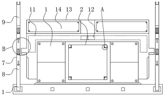
[0004] The purpose of the present invention is to provide a fault diagnosis device with an anti-magnetic field signal interference structure to solve the problem that the existing diagnosis device proposed in the background technology is not provided with a better linkage protection structure outside the main body, which leads to the main body being in the The safety and protective performance during use are not ideal, such as the anti-interference operation of magnetic field signals, etc., and the various parts of the main body cannot be reasonably connected and coordinated, which leads to the inconvenient regulation of the main body during use. Happening

Method used


Image

  • A fault diagnosis device with an anti-magnetic field signal interference structure
  • A fault diagnosis device with an anti-magnetic field signal interference structure
  • A fault diagnosis device with an anti-magnetic field signal interference structure

Examples


Embodiment Construction

[0026] The following will clearly and completely describe the technical solutions in the embodiments of the present invention with reference to the accompanying drawings in the embodiments of the present invention. Obviously, the described embodiments are only some, not all, embodiments of the present invention.

[0027] In the description of the present invention, unless otherwise stated, the meaning of "plurality" is two or more; the terms "upper", "lower", "left", "right", "inner", "outer" , "front end", "rear end", "head", "tail", etc. indicate the orientation or positional relationship based on the orientation or positional relationship shown in the drawings, and are only for the convenience of describing the present invention and simplifying the description, rather than Indicates or implies that the device or element referred to must have a particular orientation, be constructed and operate in a particular orientation, and therefore should not be construed as limiting the...


PUM


Abstract

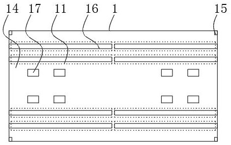
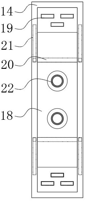
The invention relates to a fault diagnosis device with an anti-magnetic field signal interference structure, which includes a fixed seat and an anti-resistance mechanism. The middle part of the fixed seat is provided with a central separation groove, and the end of the central separation groove is connected with a central assembly mechanism. The anti-resistance mechanism is installed on the side end of the fixed seat, and the upper end of the fixed seat is provided with a hinge slot, and the inner end of the hinge slot is connected with a hinge block. The beneficial effect of the present invention is: the anti-magnetic field signal interference structure The fault diagnosis device can be connected through the two ends of the central block, that is, the peripheral devices are paired and assembled with the central block according to the screw connection holes, so that it is convenient to install diagnostic electrical components from multiple angles. At the same time, when the lifting part is not in use, the space inside the central compartment can be fully utilized for convenient storage operations, and the distance between the two can be adjusted by rotating the anti-bar and the upper hinge bar. And then change the height of the upper hinge bar.

Description

technical field [0001] The invention relates to the technical field of fault diagnosis devices, in particular to a fault diagnosis device with an anti-magnetic field signal interference structure. Background technique [0002] The magnetic field is a kind of invisible and intangible special substance. The magnetic field is not composed of atoms or molecules, but the magnetic field exists objectively. The magnetic field has the radiation characteristics of wave particles. There is a magnetic field around the magnet, and the interaction between the magnets is the magnetic field. As a medium, the two magnets can function without physical contact, and some fault diagnosis equipment for power devices generally need to interfere with the mine magnetic field signal when they are used. [0003] The existing diagnostic device is not equipped with a good linkage protection structure outside the main body, which leads to unsatisfactory safety and protection performance of the main body...

Claims


Application Information

Patent Timeline
Patent Type & Authority Patents(China)
IPC IPC(8): G01R31/00G01R31/40G01R1/04G01R1/18
CPCG01R1/0408G01R1/18G01R31/00G01R31/40
Inventor 杨帅敖文刚杨艺罗星汪羽
Owner CHONGQING TECH & BUSINESS UNIV
Learn More