Steering device and steering adjusting method for tension pay-off construction
A steering device and tension technology, applied in the direction of overhead lines/cable equipment, etc., can solve the problems such as the multi-angle and multi-dimensional adjustment requirements that cannot be well adapted to the mountainous terrain, and the limited angle adjustment range of the steering device, so as to eliminate potential safety hazards. , Improve safety and reduce damage
- Summary
- Abstract
- Description
- Claims
- Application Information
AI Technical Summary
Problems solved by technology
Method used
Image
Examples
Embodiment 1
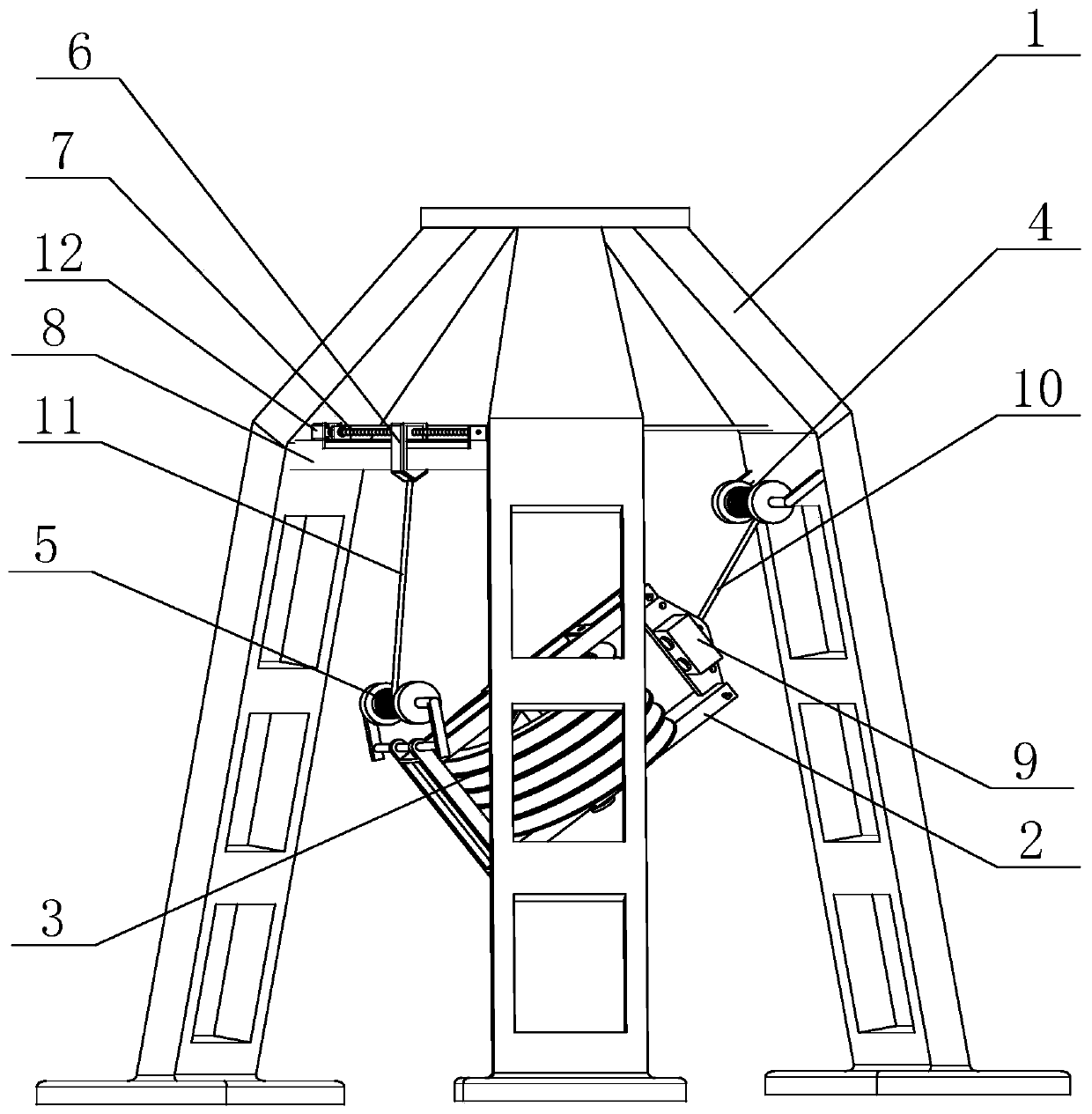
[0060] Such as figure 1 The illustrated steering device for tension pay-off construction includes a truss 1 in which a trolley frame 2 is provided, a trolley 3 is provided in the trolley frame 2, and the first end of the trolley frame 2 passes through the first The rope 10 is connected to the truss 1, and the second end of the trolley frame 2 is connected to the truss 1 through a second rope 11, and the position of the connection point of the second rope 11 on the truss 1 is adjustable.
[0061] In some embodiments, the truss includes three masts, the tops of the three masts are fixedly connected, and the bottoms of the three masts form an equilateral triangle. The structure realizes lightweight design on the basis of structural stability and reduces the transportation load of mountainous terrain.
[0062] In some embodiments, a sliding rail may be provided on the truss, and a lifting ring is provided on the sliding block of the sliding rail. The second rope passes through the lift...
Embodiment 2
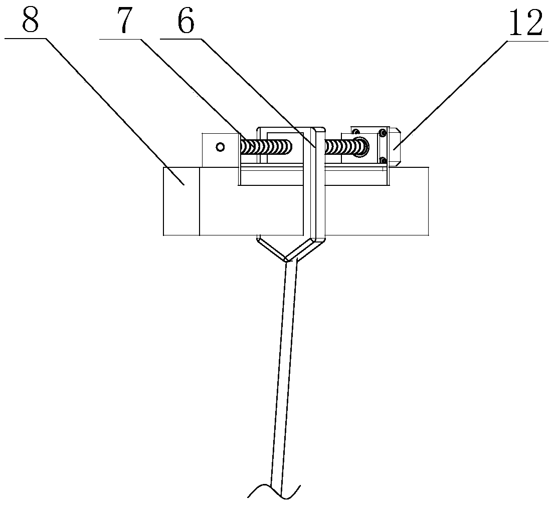
[0066] Such as figure 1 with figure 2 As shown, on the basis of Embodiment 1, the lengths of the first rope 10 and the second rope 11 are adjusted by a hoist. Wherein, the first rope 10 is connected with a fixed hoist 4, which is fixedly installed on the truss 1; a bearing frame 8 is provided on the truss 1, and a sliding block 6 is slidably arranged on the bearing frame 8. 6 is connected with a mobile hoist 5 through a second rope 11, the mobile hoist 5 is arranged on the second end of the trolley frame 2; the bearing frame 8 is provided with a ball screw 7, and the slider 6 is mounted on the ball On the nut of the screw 7.
[0067] The above arrangement makes it possible to adjust the pitch angle of the pulley even when the first rope or the second rope cannot be adjusted, to ensure the normal operation of the steering, and the reliability of the steering device is higher.
[0068] In some embodiments, two adjacent masts are connected at both ends of the carrying frame 8 to imp...
Embodiment 3
[0070] Such as figure 1 with figure 2 As shown, the steering device for tension pay-off construction includes a truss 1 in which a trolley frame 2 is provided, and a trolley 3 is provided in the trolley frame 2, and one end of the trolley frame 2 passes through the first The rope 10 is connected with a fixed hoist 4, the fixed hoist 4 is fixedly installed on the truss 1, and the other end of the trolley frame 2 is provided with a mobile hoist 5, the mobile hoist 5 is connected with a slider 6 through a second rope 11, and the slider 6 The position on the truss 1 can be adjusted; the truss 1 is provided with a bearing frame 8, the bearing frame 8 is provided with a ball screw 7 and a motor 12, and a slider 6 is mounted on the nut of the ball screw 7, the The output shaft of the motor 12 is connected to the screw of the ball screw 7; it also includes a binocular stereo camera 9 and a processor, and the processor is electrically connected with the binocular stereo camera 9, the fi...
PUM
 Abstract
Description
Claims
Application Information
 - R&D
- Intellectual Property
- Life Sciences
- Materials
- Tech Scout
- Unparalleled Data Quality
- Higher Quality Content
- 60% Fewer Hallucinations
Browse by: Latest US Patents, China's latest patents, Technical Efficacy Thesaurus, Application Domain, Technology Topic, Popular Technical Reports.
© 2025 PatSnap. All rights reserved.Legal|Privacy policy|Modern Slavery Act Transparency Statement|Sitemap|About US| Contact US: help@patsnap.com


