
Bidirectionally rotary lipstick box

A two-way rotation, lipstick box technology, applied in the direction of packaging items, applications, special packaging items, etc., can solve the problems of inability to rotate relatively, inconvenient, affecting users' use, etc., to extend service life, improve reliability, and facilitate operation. Effect

Active Publication Date: 2019-12-31
ZHEJIANG YUYAN IND DESIGN CO LTD
View PDF5 Cites 0 Cited by
  • Summary
  • Abstract
  • Description
  • Claims
  • Application Information

AI Technical Summary

Problems solved by technology

[0003] Traditional lipstick boxes mostly use a structure in which the paste rises spirally relative to the sleeve, that is, when the base is fixed and the sleeve is rotated, the lipstick rises vertically or when the sleeve is fixed and the base is rotated, the lipstick paste rises spirally. After rising or falling in place, the sleeve Due to structural limitations, the base and the base cannot rotate relative to each other. If excessive rotational force is applied, the connection between the sleeve and the base will be destroyed, and the paste cannot be lifted or retracted, which will affect the user's use
[0004] Usually, lipsticks have a beautiful appearance and a sweet smell. Apart from being loved by beauty lovers, they will also attract the attention of children. When placed carelessly, lipsticks are easily taken away by children to play with, because children like it when twisting things. Continuous twisting will not give up because it cannot be twisted, so lipsticks with stop settings are easy to be twisted; traditional lipsticks need to twist the base 360° to realize the entire paste out of the sleeve, which is more efficient to use low, less convenient

Method used


Image

  • Bidirectionally rotary lipstick box
  • Bidirectionally rotary lipstick box
  • Bidirectionally rotary lipstick box

Examples


Embodiment Construction

[0028] The technical solution of the present invention will be further specifically described below through specific implementation modes (embodiments) and in conjunction with the accompanying drawings.

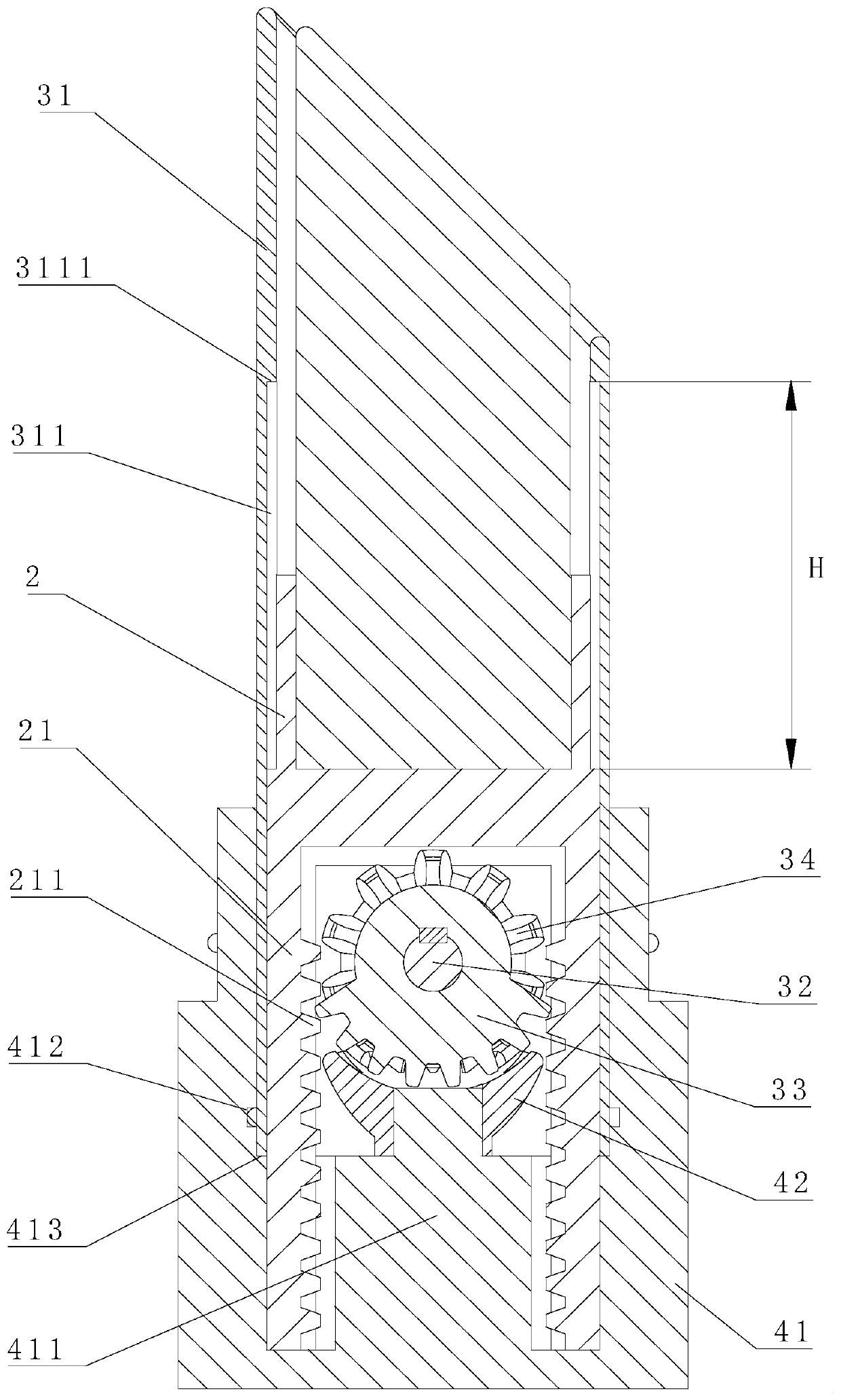
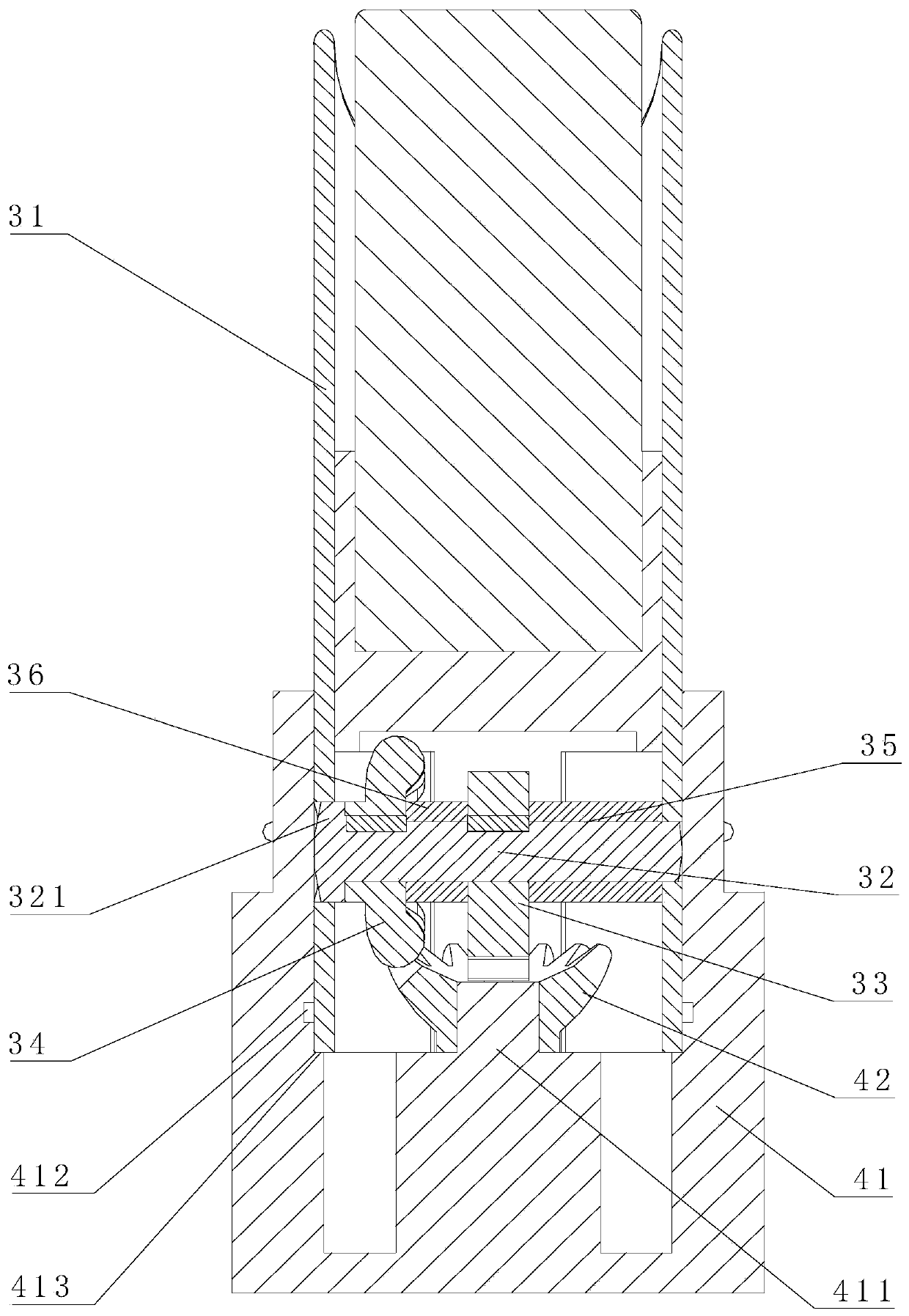
[0029] A traditional lipstick box mainly includes a top cover 1, a lipstick paste holder 2, a sleeve assembly 3 and a rotating base assembly 4, see Figure 1-8 The outer periphery of the lower end of the lipstick paste bracket 2 of the two-way rotary lipstick box provided by the present invention is provided with two oppositely arranged protruding ends 21, and the inner side of the protruding ends 21 is provided with a rack 211; the sleeve assembly 3 includes Sleeve 31, the sleeve 31 is a circular tube with the upper end chamfered, the lower part of the sleeve 31 is provided with a rotating shaft 32 passing through the center of the sleeve 31, and the two ends are framed on the side wall of the sleeve 31, the rotating shaft 32 The middle part is fixedly connected with a secto...


PUM


Abstract

The invention relates to a bidirectionally rotary lipstick box. Two extension ends arranged oppositely are arranged in the periphery of the lower end of a lipstick box support; a rack is arranged on the inner side of each extension end; a sleeve component comprises a sleeve that is a round tube with an aslant cut upper end; a rotation shaft passing through the center of the sleeve and of which twoends are arranged on the side wall of the sleeve is arranged at the lower part of the sleeve; a fan-shaped gear matched with the racks is fixedly connected with the middle part of the rotation shaft;a small bevel gear is fixedly connected to one end of the rotation shaft in the sleeve; and a rotary pedestal component comprises a pedestal that is designed to be hollow, a cylindrical bump is arranged at the bottom of the pedestal, and a big bevel gear is fixedly connected to the upper end of the cylindrical bump. Via continuous rotation of the pedestal in any direction, the lipstick box provided by the invention can be repeatedly moved up and down, so that the reliability of the lipstick box is improved, and the service life of the lipstick box is prolonged; and by rotating the pedestal for a relatively small angle, a lifting process of the lipstick box can be achieved, and the lipstick box is high in efficiency and more convenient to operate.

Description

technical field [0001] The invention relates to lipstick box production technology, in particular to the manufacture and use of a two-way rotary lipstick box. Background technique [0002] With the gradual improvement of people's living standards, the requirements of the majority of ladies for cosmetics are also gradually increasing. As the most brilliant lipstick in cosmetics, when users choose, they not only value the color of the paste, but also the aesthetics and convenience of the lipstick box. [0003] Traditional lipstick boxes mostly use a structure in which the paste rises spirally relative to the sleeve, that is, when the base is fixed and the sleeve is rotated, the lipstick rises vertically or when the sleeve is fixed and the base is rotated, the lipstick paste rises spirally. After rising or falling in place, the sleeve Due to structural limitations, it cannot rotate relative to the base. If excessive rotational force is applied, the connection between the sleev...

Claims


Application Information

Patent Timeline
Patent Type & Authority Applications(China)
IPC IPC(8): A45D40/06
CPCA45D40/065
Inventor 梅丽莎梅巨魏
Owner ZHEJIANG YUYAN IND DESIGN CO LTD
Learn More