A stamping die with convenient blanking

A stamping die, a convenient technology, applied in the field of stamping dies, can solve the problems of waste materials scattered on the ground or around the loading box, affecting the processing accuracy and efficiency of the product, and affecting the accuracy of the mold, so as to improve the structural strength and reliability, and strengthen the structure , the effect of increasing life

Active Publication Date: 2020-11-27
东莞市伟峰印刷有限公司
View PDF6 Cites 0 Cited by
  • Summary
  • Abstract
  • Description
  • Claims
  • Application Information

AI Technical Summary

Problems solved by technology

[0002] The stamping die is divided into a lower die and an upper die. Generally, the upper and lower dies have a specific shape, but in general, the lower die has a general shape, and the upper die directly uses a flat plate to directly extrude the stamping process. At this time, the stamping The mold has many disadvantages. For example, when the stamping mold is actually working, it is necessary to frequently replace the lower mold to realize the processing of different products. Rapid processing will cause the waste to be scattered on the ground or around the loading box, so that the personnel have to spend time and energy to clean the waste. The structure will cause the lower mold to be subjected to deformation force during the stamping process and affect the precision of the lower mold, which will affect the precision and efficiency of product processing when the equipment is working continuously

Method used


Image

  • A stamping die with convenient blanking
  • A stamping die with convenient blanking
  • A stamping die with convenient blanking

Examples


Embodiment Construction

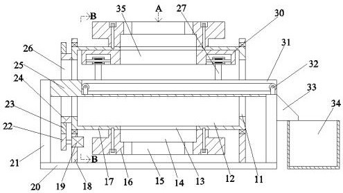
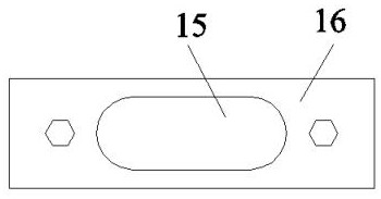
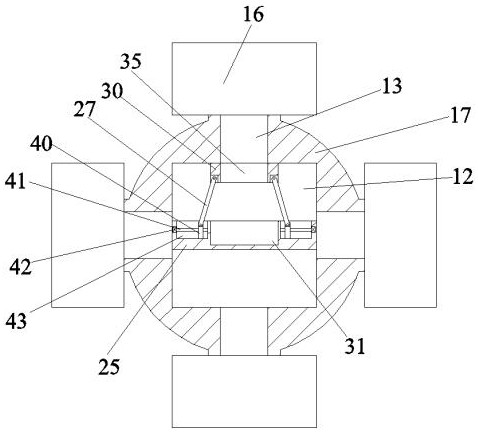
[0020] Such as Figure 1-Figure 3 As shown, the present invention is described in detail. For the convenience of description, the orientations mentioned below are now stipulated as follows: figure 1 The up, down, left, right, front and back directions of the projection relationship itself are consistent. A stamping die for convenient blanking of the present invention includes a symmetrically arranged vertical plate 18, and a rotary cylinder 17 is provided for rotation in the vertical plate 18. The rotary cylinder 17 is provided with a cavity 12, the end wall of the cavity 12 is connected with a number of open grooves 13, the open groove 13 is connected with the external space, and the end walls on both sides of the cavity 12 are connected with an inner cavity 11 , the inner cavity 11 is symmetrically arranged, the outer surface of the vertical plate 18 and the rotating cylinder 17 is provided with a rotating device that drives the rotating cylinder 17 to rotate, and the lower ...


PUM


Abstract

The invention discloses a stamping die facilitating to blanking. The stamping die facilitating to blanking comprises vertical plates which are symmetrically arranged, wherein a rotary barrel is rotationally arranged in each vertical plate; an accommodating cavity is formed in each rotary barrel; a plurality of open grooves are formed in the end wall of each accommodating cavity in a communicationmanner; the open grooves communicate with an external space; inner cavities are formed in the end walls of the two sides of each accommodating cavity in a communication manner; the inner cavities aresymmetrically formed; and rotary devices driving the rotary barrels to rotate are arranged on the outer surfaces of the vertical plates and the rotary barrels. The equipment is simple in structure; easier blanking machining is realized by adopting the manner of replacing dies with different shapes and dimensions by means of rotating, and a lower die does not need to be manually replaced; and moreover, wastes are rapidly guided out of the equipment in a blanking process, and the lower die plays the role of structure enhancement during stamping for the equipment, so that the structure strength and reliability during continuous blanking of the die are effectively improved, and the life of the die is prolonged.

Description

technical field [0001] The invention relates to the technical field of stamping, in particular to a stamping die with convenient blanking. Background technique [0002] The stamping die is divided into a lower die and an upper die. Generally, the upper and lower dies have a specific shape, but in general, the lower die has a general shape, and the upper die directly uses a flat plate to directly extrude the stamping process. At this time, the stamping The mold has many disadvantages. For example, when the stamping mold is actually working, it is necessary to frequently replace the lower mold to realize the processing of different products. Rapid processing will cause the waste to be scattered on the ground or around the loading box, so that the personnel have to spend time and energy to clean the waste. The structure will cause the lower mold to be subjected to deformation force during the stamping process and affect the precision of the lower mold, which will affect the pr...

Claims


Application Information

Patent Timeline
Patent Type & Authority Patents(China)
IPC IPC(8): B21D28/14B21D45/06
CPCB21D28/14B21D45/06
Inventor 胡月明
Owner 东莞市伟峰印刷有限公司
Why Eureka
Try Eureka