Supercharge Your Innovation With Domain-Expert AI Agents!

A welding process in electronic detonator chip assembly

An electronic detonator and welding process technology, applied in welding equipment, welding equipment, auxiliary welding equipment, etc., can solve the problems of low welding efficiency, inconvenient workpiece fixing, and low workpiece protection, so as to improve welding efficiency, facilitate fixing, and ensure Check the effect of quality

Active Publication Date: 2022-04-08
贵州瑞讯科技有限公司
View PDF6 Cites 0 Cited by
  • Summary
  • Abstract
  • Description
  • Claims
  • Application Information

AI Technical Summary

Problems solved by technology

[0004] Aiming at the deficiencies of the prior art, the present invention provides a welding process in electronic detonator chip assembly, which has the advantages of improving the protection of workpieces, improving welding efficiency, facilitating the fixing of workpieces, and ensuring the quality of inspection. It solves the problem that in the traditional electronic detonator chip assembly and welding technology scheme, the protection of the workpiece is low, the welding efficiency is low, it is not convenient to fix the workpiece, and the inspection quality cannot be guaranteed

Method used


Image

  • A welding process in electronic detonator chip assembly

Examples


Embodiment 1

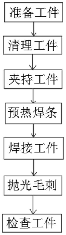
[0031] see figure 1 , a welding process in electronic detonator chip assembly, including preparing workpieces—cleaning workpieces—clamping workpieces—preheating electrodes—welding workpieces—polishing burrs—checking workpieces, and the specific steps are as follows:

[0032] (1) Prepare the workpiece: take out the electronic detonator components and electronic detonator chips that need to be welded, and place them on the workbench for standby;

[0033] (2) Clean up the workpiece: place the electronic detonator assembly and the electronic detonator chip placed on the workbench selected in step (1) on the hand, and check the sundries at the welding position of the electronic detonator assembly and the electronic detonator chip or dust cleaning;

[0034] (3) Clamp the workpiece: move the electronic detonator assembly and the electronic detonator chip that have been cleaned in step (2) to the lower end of the clamping device placed on the workbench, and hold the electronic detona...

Embodiment 2

[0044] A welding process in the assembly of electronic detonator chips, including preparing workpieces—cleaning workpieces—clamping workpieces—preheating electrodes—welding workpieces—polishing burrs—checking workpieces, and the specific steps are as follows:

[0045] (1) Prepare the workpiece: take out the electronic detonator components and electronic detonator chips that need to be welded, and place them on the workbench for standby;

[0046](2) Clean up the workpiece: place the electronic detonator assembly and the electronic detonator chip placed on the workbench selected in step (1) on the hand, and check the sundries at the welding position of the electronic detonator assembly and the electronic detonator chip or dust cleaning;

[0047] (3) Clamp the workpiece: move the electronic detonator assembly and the electronic detonator chip that have been cleaned in step (2) to the lower end of the clamping device placed on the workbench, and hold the electronic detonator assem...


PUM

PropertyMeasurementUnit
diameteraaaaaaaaaa
diameteraaaaaaaaaa
heightaaaaaaaaaa

Abstract

The invention relates to the technical field of electronic detonator chip assembly, and discloses a welding process in electronic detonator chip assembly, including preparing workpieces—cleaning workpieces—clamping workpieces—preheating electrodes—welding workpieces—polishing burrs—inspecting workpieces. In the welding process in the assembly of electronic detonator chips, when the burrs are polished, the shielding plate is placed on the workbench to shield the electronic detonator components and electronic detonator chips other than the welding position, allowing them to be welded by wire brushes. When the position is polished, it will not be brushed to other places, so as to avoid damage to the electronic detonator components and electronic detonator chips caused by the steel wire brushing to other places, improve the protection of the workpiece, improve the welding efficiency, and facilitate the fixing of the workpiece. And can guarantee the quality of inspection.

Description

technical field [0001] The invention relates to the technical field of electronic detonator chip assembly, in particular to a welding process in electronic detonator chip assembly. Background technique [0002] Electronic detonators, also known as digital electronic detonators, digital detonators or industrial digital electronic detonators, are electric detonators that use electronic control modules to control the detonation process. In the existing electronic detonator chip assembly and welding technical solutions, the protection of workpieces is low. The welding efficiency is low, it is not convenient to fix the workpiece, and the inspection quality cannot be guaranteed. For this reason, we propose a welding process in electronic detonator chip assembly. Contents of the invention [0003] (1) Solved technical problems [0004] In view of the deficiencies of the prior art, the present invention provides a welding process in electronic detonator chip assembly, which has ...

Claims


Application Information

Patent Timeline
Patent Type & Authority Patents(China)
IPC IPC(8): B23K31/02B23K37/00
CPCB23K31/02B23K37/00
Inventor 陈庆杨连奇
Owner 贵州瑞讯科技有限公司
Features
  • R&D
  • Intellectual Property
  • Life Sciences
  • Materials
  • Tech Scout
  • Unparalleled Data Quality
  • Higher Quality Content
  • 60% Fewer Hallucinations
Learn More