
Wire end tightening humanoid robot and using method thereof

A technology for simulating robots and thread heads, applied in the field of gripping jaws, can solve the problems of high tape fixing stability, high cylinder power requirements, low cutting stability, etc., to achieve rich performance, wide usable range, and improved flexibility. Effect

Active Publication Date: 2019-12-31
SUZHOU JIANGJIN AUTOMATION TECH
View PDF7 Cites 8 Cited by
  • Summary
  • Abstract
  • Description
  • Claims
  • Application Information

AI Technical Summary

Problems solved by technology

[0004] After the winding is completed, when the thread end is cut off, the thread is cut off by the cutting device on the automatic loading and unloading robot of the reel, but for the metal wire, the conventional shearing knife is often not easy to cut quickly, and the power of the cylinder The requirements are high, the cutting stability is not high, and the scope of application is limited
[0005] After cutting, the thread ends on the winding reel are attached by the tape sticking device, but there is a risk that the thread ends will loosen from the tape when the tape sticking device is attached, which requires high fixing stability of the tape; also increased cost

Method used


Image

  • Wire end tightening humanoid robot and using method thereof
  • Wire end tightening humanoid robot and using method thereof
  • Wire end tightening humanoid robot and using method thereof

Examples


Embodiment Construction

[0063] Objects, advantages and features of the present invention will be illustrated and explained by the following non-limiting description of preferred embodiments. These embodiments are only typical examples of applying the technical solutions of the present invention, and all technical solutions formed by adopting equivalent replacements or equivalent transformations fall within the protection scope of the present invention.

[0064] In the description of the scheme, it should be noted that the terms "center", "upper", "lower", "left", "right", "front", "rear", "vertical", "horizontal", " The orientation or positional relationship indicated by "inner", "outer", etc. is based on the orientation or positional relationship shown in the drawings, and is only for the convenience of description and simplification of description, rather than indicating or implying that the device or element referred to must have a specific orientation , constructed and operated in a particular or...


PUM


Abstract

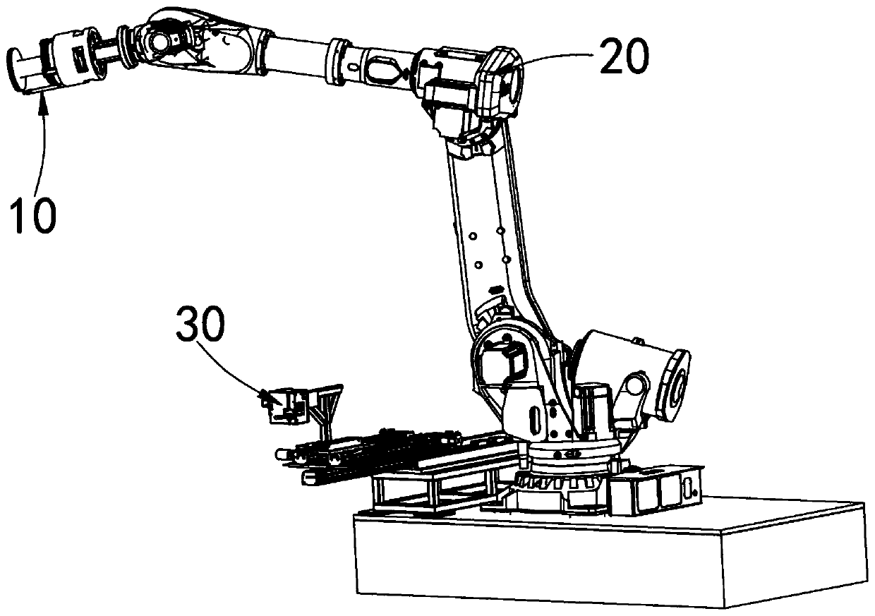
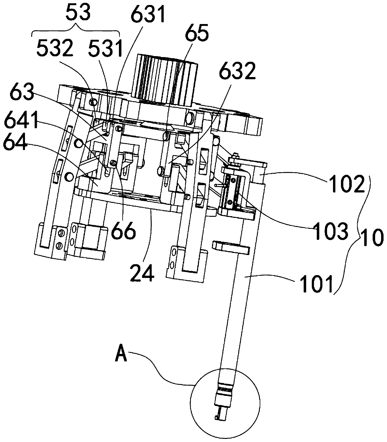
The invention discloses a wire end tightening humanoid robot and a using method thereof. The humanoid robot comprises a wire end gripping device, a moving device for driving the wire end gripping device and a guide fusing device, wherein the guide fusing device comprises an upper partition column, a lower partition column and a fusing device body, and a height difference is generated between the upper partition column and the lower partition column. In a first state, the upper partition column and the lower partition column can cooperate with at least one side plate to limit a wire from movingoutwards from the inside of the guide fusing device; in a second state, notches at same positions are formed in the upper partition column and the lower partition column so as to allow the wire to pass through; and the fusing device body can fuse the wire between the upper partition column and the lower partition column when the upper partition column and the lower partition column are in the first state. According to the scheme, manual work can be simulated to tighten wire ends, therefore, the wire end fixing firmness can be ensured, packaging tape is not required in use, and the cost is low. The wire is cut off by combining with a hot fusing way, the cutting requirements of various materials, such as metal, can be effectively met, the cutting stability is high, and the application rangeis wide.

Description

technical field [0001] The invention relates to the field of grippers, in particular to a thread-tightening simulation robot and a use method thereof. Background technique [0002] For various silk and thread products, it is often necessary to wind the silk and thread onto the winding reel to form the final product. The existing various winding machines can effectively wind the thread and thread, but before winding , It is often necessary to manually place the winding reel on the winding machine or remove the winding reel on the winding machine from the winding machine. The method of manually loading and unloading the winding reel requires special personnel to operate, which increases the labor cost of the enterprise and labor Strong, contrary to the current industrial development trend of automation and intelligence. [0003] In order to realize automatic winding, the applicant applied for the following application number 201811552218.2 for a fully automatic winding produc...

Claims


Application Information

Patent Timeline
Patent Type & Authority Applications(China)
IPC IPC(8): B25J11/00B25J15/00B25J15/08B65H75/00
CPCB25J11/00B65H75/00B25J15/00B25J15/08
Inventor 黄冬梅刘玉飞苏高峰陈中杰
Owner SUZHOU JIANGJIN AUTOMATION TECH
Learn More