A punching device with protective function

A technology of punching equipment and protective functions, which is applied in metal processing and other directions, can solve the problems of reduced practicability of punching equipment, hot workpiece surface, and increased surface temperature, so as to facilitate repeated heat absorption and cooling, prevent jitter offset, The effect of improving machining accuracy

Active Publication Date: 2021-07-30
南京江宁区上峰国银标准件厂
View PDF0 Cites 0 Cited by
  • Summary
  • Abstract
  • Description
  • Claims
  • Application Information

AI Technical Summary

Problems solved by technology

[0003] When the existing drilling equipment is drilling the workpiece, after the rotating drill rod comes into contact with the workpiece, it is easy to generate splashing debris. Due to high temperature friction, the temperature of these debris is high, and when it splashes out, it is easy to damage the The surrounding operators cause injuries, not only that, due to the frictional contact between the drill pipe and the workpiece, the surface temperature of the drill pipe and the workpiece increases. After the temperature rises, the surface of the workpiece becomes hot, which not only causes deformation of the workpiece, but also causes furniture drilling Rod wear, which in turn reduces the usefulness of existing punching equipment

Method used


Image

  • A punching device with protective function
  • A punching device with protective function
  • A punching device with protective function

Examples


Embodiment Construction

[0024] The present invention is described in further detail now in conjunction with accompanying drawing. These drawings are all simplified schematic diagrams, which only illustrate the basic structure of the present invention in a schematic manner, so they only show the configurations related to the present invention.

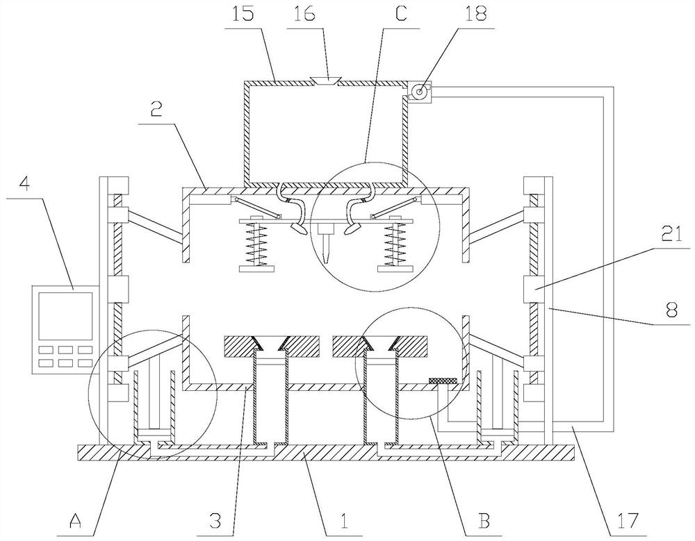
[0025] Such as figure 1 As shown, a drilling device with a protective function includes a base 1, an upper shell 2, a lower shell 3, a controller 4, a placement mechanism, a cooling mechanism, a lifting mechanism, a lifting plate 5, a motor 6, a drill rod 7 and two a vertical board 8, the vertical board 8 is fixed above the base 1, the controller 4 is fixed on one of the vertical boards 8, the controller 4 is provided with a PLC, and the controller 4 is provided with a display screen and a number of keys, the motor 6, the display screen and the keys are all electrically connected to the PLC, the upper shell 2 and the lower shell 3 are relatively arranged betw...


PUM


Abstract

The invention relates to a drilling device with protective function, which includes a base, an upper shell, a lower shell, a placing mechanism, a cooling mechanism, a lifting mechanism, a lifting plate, a motor, a drill rod and two vertical plates. The placing mechanism includes a platform and two A supporting component, the cooling mechanism includes a water tank, a sealing plug, a return pipe, a water pump and several cooling components, the cooling component includes a nozzle and a cooling tube, and the punching device with a protective function can drive the upper shell and the lower shell during processing through the driving mechanism Close to each other to form a closed processing environment, to prevent debris from splashing and endangering surrounding personnel, to ensure processing safety, and to drive the placement mechanism to fix the workpiece to prevent the workpiece from shaking and shifting, and to use the cooling mechanism to spray water to absorb the heat of the workpiece and the drill pipe to cool down. Extend the life of the drill pipe and improve the machining accuracy. Since the water is sprayed in a closed environment to prevent the water from splashing to the outside, it is convenient to recycle the water for repeated heat absorption and cooling, which improves the practicability of the equipment.

Description

technical field [0001] The invention relates to the field of mechanical equipment, in particular to a punching equipment with protective function. Background technique [0002] Drilling machine is a general term for machinery and equipment that uses a tool that is harder and sharper than the target to leave a cylindrical hole or hole on the target by means of rotary cutting or rotary extrusion. Also known as punching machine, drilling machine, through hole machine and so on. The desired effect is achieved by drilling precision parts. [0003] When the existing drilling equipment is drilling the workpiece, after the rotating drill rod comes into contact with the workpiece, it is easy to generate splashing debris. Due to high temperature friction, the temperature of these debris is high, and when it splashes out, it is easy to damage the The surrounding operators cause injuries, not only that, due to the frictional contact between the drill pipe and the workpiece, the surfac...

Claims


Application Information

Patent Timeline
Patent Type & Authority Patents(China)
IPC IPC(8): B26F1/16B26D7/02B26D7/08B26D7/22
CPCB26D7/02B26D7/08B26D7/22B26F1/16
Inventor 韩平
Owner 南京江宁区上峰国银标准件厂
Why Eureka
Try Eureka