Nonmagnetic bearing, centerless fixture and nonmagnetic bearing manufacturing method

A centerless fixture and manufacturing method technology, applied in the field of bearings, can solve the problems of wireless charging rotor vibration and noise, poor structural design and manufacturing quality, etc., and achieve the effects of satisfying processing design requirements, improving running trajectory, and improving processing accuracy.

Pending Publication Date: 2019-12-31
上海赛姆轴承有限公司
View PDF0 Cites 4 Cited by
  • Summary
  • Abstract
  • Description
  • Claims
  • Application Information

AI Technical Summary

Problems solved by technology

[0004] In order to solve the technical problem that the high-speed rotating wireless charging rotor will generate vibration and noise due to the poor structural design and manufacturing quality of the ceramic balls and inner and outer rings of the deep-groove ceramic ball non-magnetic bearing after a large number of wireless charging systems are installed in the garage, the present invention provides a A non-magnetic bearing, made of non-magnetic materials, including: an outer ring, an inner ring, a cage and ceramic balls, a first groove is arranged in the circumferential direction of the center of the inner diameter of the outer ring, and a first groove is arranged in the circumferential direction of the center of the outer diameter of the inner ring. The groove fits the second groove, and the ceramic ball is fixed between the first groove and the second groove at intervals through the cage, wherein the curvature coefficient of the first groove is greater than the curvature coefficient of the second groove, and the first groove The curvature coefficient of the groove is 0.525-0.510, and the curvature coefficient of the second groove is 0.515-0.505

Method used


Image

  • Nonmagnetic bearing, centerless fixture and nonmagnetic bearing manufacturing method
  • Nonmagnetic bearing, centerless fixture and nonmagnetic bearing manufacturing method
  • Nonmagnetic bearing, centerless fixture and nonmagnetic bearing manufacturing method

Examples


Embodiment 1

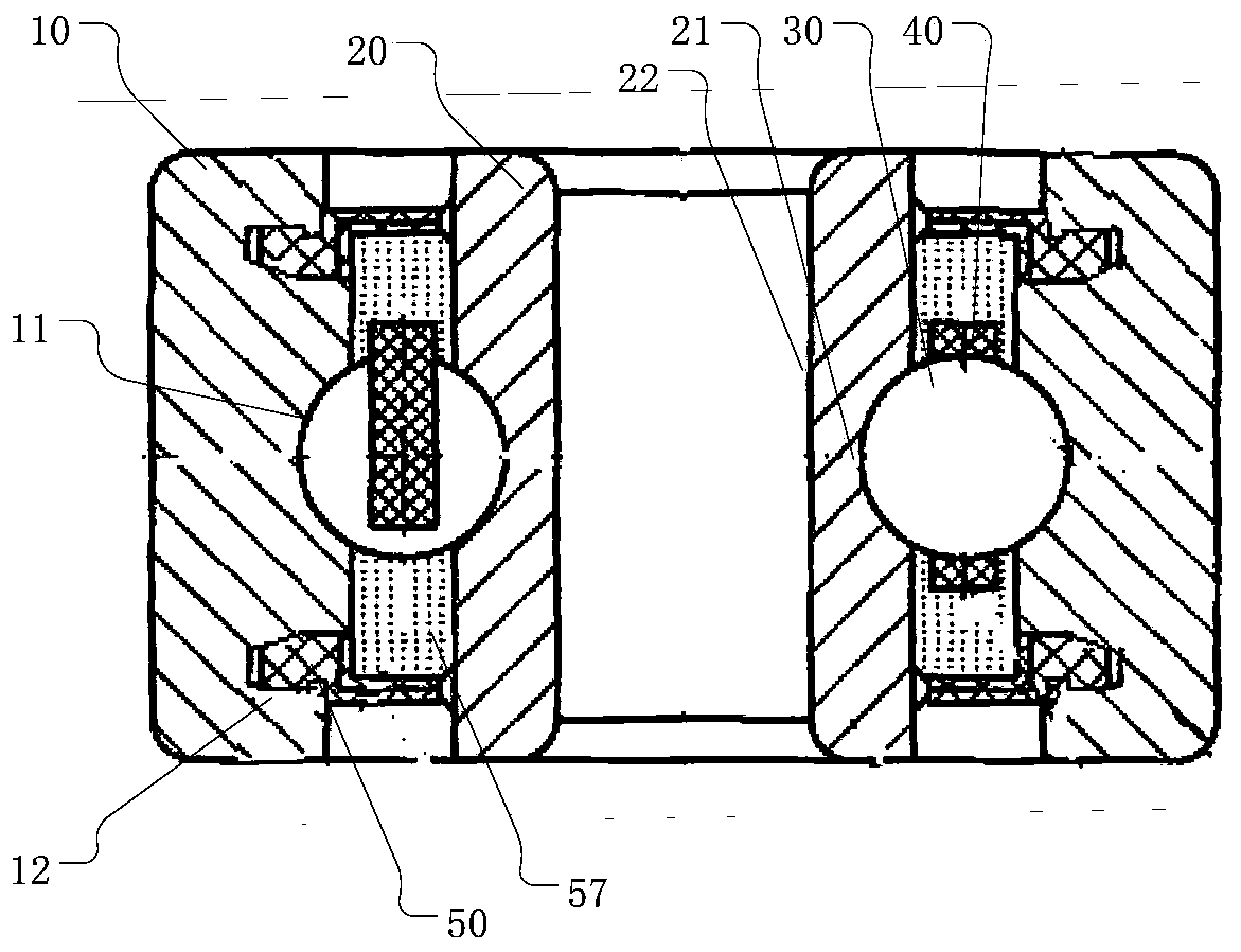
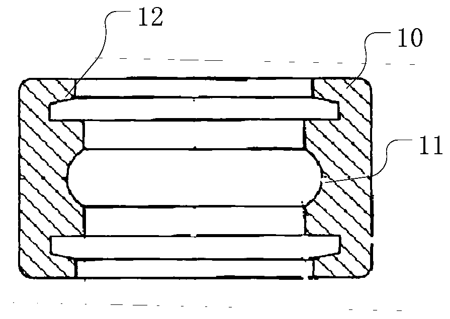
[0058] The embodiment of the present invention provides a non-magnetic bearing, which is made of non-magnetic materials, such as figure 1 As shown, it includes: an outer ring 10 , an inner ring 20 , a cage 40 and ceramic balls 30 .

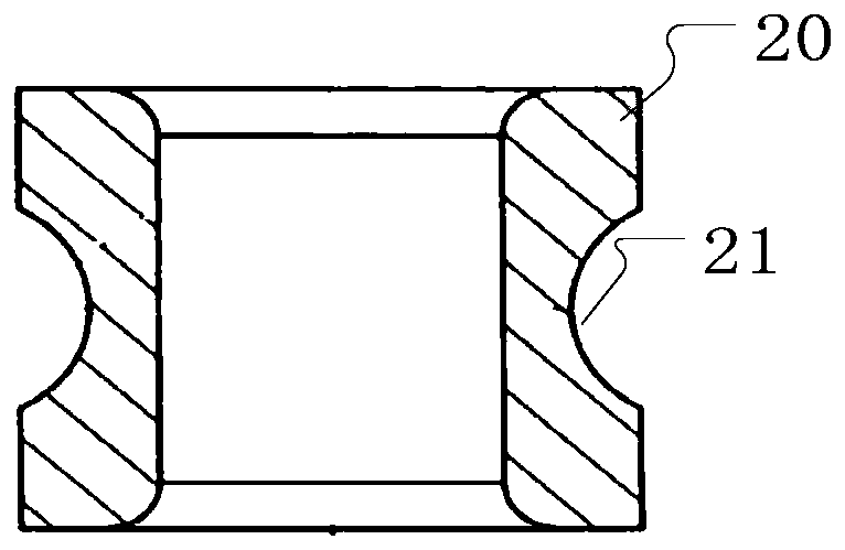
[0059] A first groove 11 is provided in the circumferential direction of the center of the inner diameter of the outer ring 10 , and a second groove 21 matching the first groove 11 is provided in the circumferential direction of the center of the outer diameter of the inner ring 20 . It should be noted that, here, the center of the inner diameter of the outer ring 10 refers to the center of the inner diameter surface, and the center of the outer diameter of the inner ring 20 refers to the center of the outer diameter surface. Specifically, such as Figure 2-3 As shown, the outer ring 10 and the inner ring 20 are made of non-magnetic materials, such as Fe—Mn—Cr—C series austenitic stainless steel materials. Optionally, the outer ring 10 and the i...

Embodiment 2

[0066] This embodiment provides a non-magnetic bearing, which includes, in addition to the non-magnetic bearing provided in Embodiment 1, seal rings 50 disposed between the inner ring 20 and the outer ring 10 and on both sides of the ceramic ball 30 .

[0067] There are two sealing rings 50, and grease 57 is filled in the space surrounded by the two sealing rings 50, the inner ring 20 and the outer ring 10, thereby improving the life of the bearing and preventing the rotor from vibrating under high-speed rotation. Specifically, such as figure 1 with Image 6 As shown, the sealing ring 50 can be made of nitrile rubber, butyl rubber or EPDM rubber. Optionally, the sealing ring 50 is made of EPDM. The outer diameter surface 55 of the sealing ring 50 is provided with a flexible lip 51 , and the inner diameter surface 56 of the sealing ring 50 is in clearance fit with the outer diameter of the inner ring 20 . The inner diameter of the outer ring 10 is circumferentially provided...

Embodiment 3

[0074] The groove processing of conventional bearing steel outer ring or inner ring is to fix the outer ring or inner ring on the rotating positioning ring 91 of the machine tool by electromagnetic fixture, and then use the grinding wheel 92 for grinding. However, since the outer ring 10 and the inner ring 20 are made of non-magnetic materials, an electromagnetic chuck cannot be used. At the same time, because the spring chuck is affected by the radial runout of the main shaft 93, it is difficult to ensure the machining accuracy of the first groove 11 of the outer ring 10, the second groove 21 of the inner ring, and the inner diameter of the inner ring during the grinding process. As a result, the manufacturing quality of the non-magnetic bearing is poor, and the quality requirements of the non-magnetic bearing cannot be met.

[0075] After repeated research, the embodiment of the present invention also designs and manufactures a centerless clamp, which is used to fix the inne...


PUM

PropertyMeasurementUnit
magnetic permeabilityaaaaaaaaaa
surface roughnessaaaaaaaaaa
Rockwell hardnessaaaaaaaaaa

Abstract

The invention provides a nonmagnetic bearing and relates to the technical field of bearings. The nonmagnetic bearing comprises an outer ring, an inner ring, a holder and a ceramic ball. A first grooveis formed in the circumferential direction of the center of the inner diameter of the outer ring. A second groove matched with the first groove is formed in the circumferential direction of the center of the outer diameter of the inner ring. The ceramic ball is fixed between the first groove and the second groove in a spaced mode through the holder. The curvature coefficient of the first groove is larger than that of the second groove. The curvature of the first groove is 0.525-0.510. the curvature of the second groove is 0.515-0.505. the inner ring and the outer ring are improved to be madeof nonmagnetic materials, the curvature coefficients of the first groove of the outer ring and the second groove of the inner ring are lowered, thus the movement track of the ceramic ball in the normal direction of the contact position of the ceramic ball and the outer ring is improved, bearing vibration is lowered, and then noise generated by vibration of a wireless charging rotor rotating at a high speed is lowered. The invention further provides a centerless fixture used for machining the nonmagnetic bearing and a manufacturing method of the nonmagnetic bearing.

Description

technical field [0001] The invention relates to the technical field of bearings, and more specifically, to a non-magnetic bearing, a centerless clamp and a manufacturing method of the non-magnetic bearing. Background technique [0002] The promotion and use of electric vehicles has become one of the topics that people are most concerned about. In order to promote the development of new energy vehicles and solve the problem that the connection and maintenance of wired charging lines are cumbersome and expensive, more and more companies have carried out technical research on wireless charging. The core principle is to use the principle of electrode coupling to conduct near Distance wireless transmission. One of the coupling methods is that the terminal coupler rotates at a high speed after being powered on, and couples with the other coupler paired with the high-speed rotating end to generate a current after high-speed rotation. This generated current is one of the best optio...

Claims


Application Information

Patent Timeline
Patent Type & Authority Applications(China)
IPC IPC(8): F16C19/02F16C33/32F16C33/44F16C33/78B23Q3/06B23P15/00
CPCB23P15/00B23Q3/062F16C19/02F16C33/32F16C33/44F16C33/7823
Inventor 毛大德张辅忠王海军田静李伟贾秋生戴崇华
Owner 上海赛姆轴承有限公司
Why Eureka
Try Eureka