
Heat exchanger and draught fan

A heat exchanger and heat exchange medium technology, applied in the direction of heat exchanger shell, indirect heat exchanger, heat exchanger type, etc., can solve problems such as difficult breakthroughs

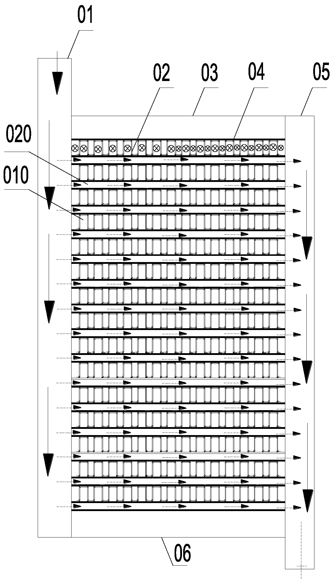
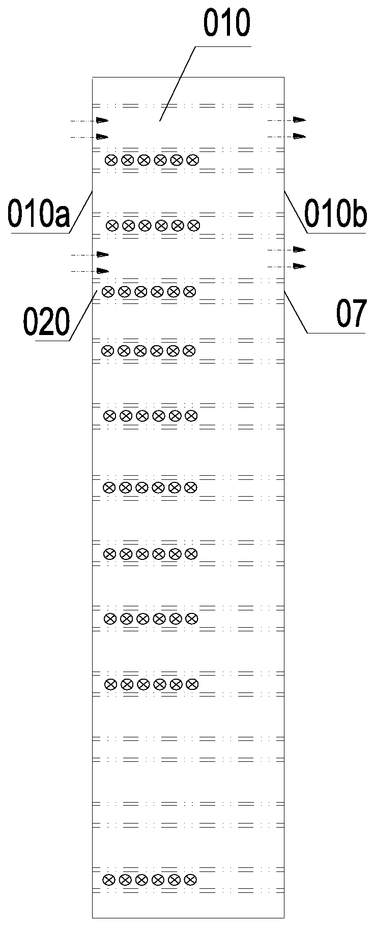
Active Publication Date: 2019-12-31
BEIJING GOLDWIND SCI & CREATION WINDPOWER EQUIP
View PDF6 Cites 0 Cited by
  • Summary
  • Abstract
  • Description
  • Claims
  • Application Information

AI Technical Summary

Problems solved by technology

The setting of the heat exchanger is always carried out around increasing ε, generally by changing the fin 02 style, the material of the fin 02 and the separator 04, etc., but it is difficult to make further breakthroughs

Method used


Image

  • Heat exchanger and draught fan
  • Heat exchanger and draught fan
  • Heat exchanger and draught fan

Examples


Embodiment Construction

[0067] In order to enable those skilled in the art to better understand the technical solutions of the embodiments of the present invention, the present invention will be further described in detail below in conjunction with the accompanying drawings and specific embodiments.

[0068] The inventors of the present application aimed at the current situation that the heat exchange effect of plate-fin heat exchangers is difficult to break through. From the perspective of combining fluid mechanics and heat transfer, the inventors of the present application found another way to find an optimized way. Therefore, before discussing specific embodiments, first describe The inventors of the present application explored the process of other possible factors affecting the efficiency of plate-fin heat exchangers.

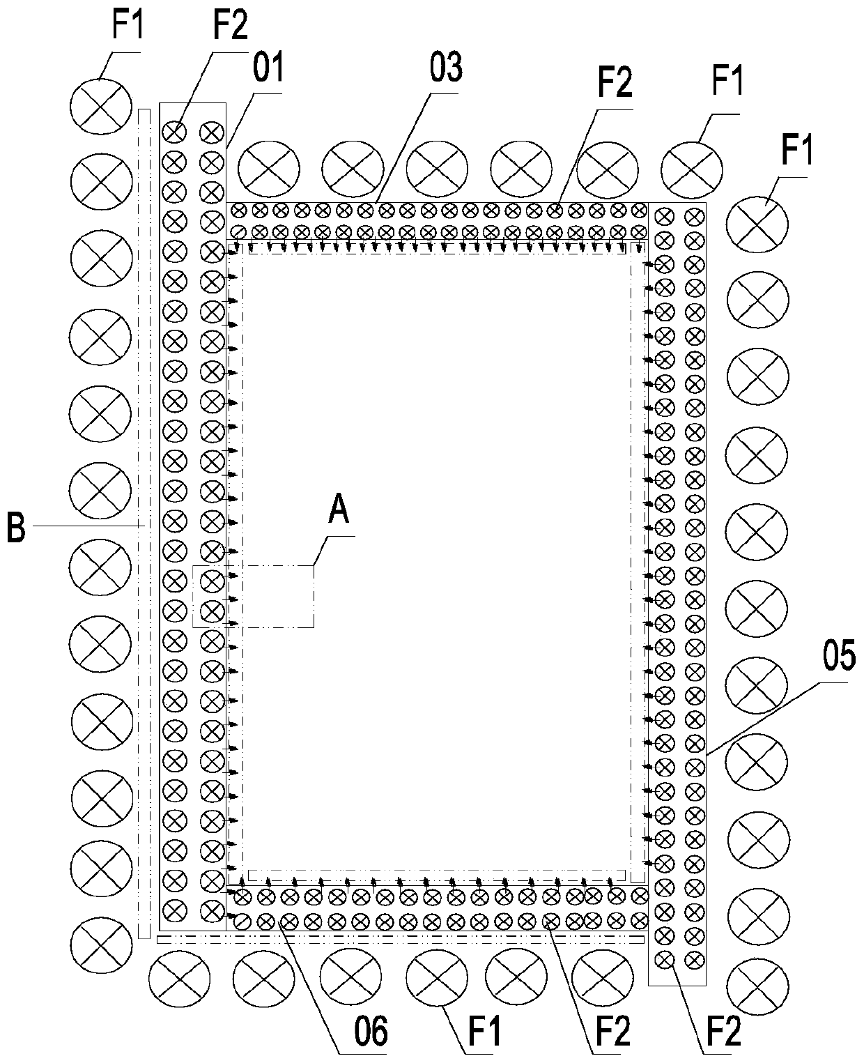
[0069] Please continue to view image 3 , image 3 head on for air figure 1 A schematic diagram of a support frame of a plate-fin heat exchanger, the support frame includes a ...


PUM


Abstract

The invention discloses a heat exchanger and a draught fan. At least two heat exchanging flow passages are formed, a corresponding heat exchanging medium flows from the external of the heat exchangerto the corresponding heat exchanging flow passage, the heat exchanger is provided with an incident flow side facing the heat exchanging medium, the incident flow side is provided with an anti-frontalimpact guide part to prevent the heat exchanging medium from frontal impact, and the corresponding heat exchanging medium is introduced into the corresponding heat exchanging flow passage. According to the heat exchanger and the draught fan, the airflow inlet boundary is renovated, unique laws of fluid mechanics and facts reflected by a boundary layer theory are followed, local resistance to a fluid at an incident flow interface can be lowered, separation generated by flow direction normal impact, transverse resistance and vertical resistance formed by the separation are lowered, the requiredthrough-flow flux and the required through-flow rate are obtained by making full use and with the help of the inflow velocity or a fluid transport machine, local resistance caused by the fluid transfer and heat exchanging link and process on the incident flow face is lowered, and finally, the heat exchanging effect of the heat exchanger is improved.

Description

technical field [0001] The invention relates to the technical field of heat exchange, in particular to a heat exchanger and a fan. Background technique [0002] The plate-fin heat exchanger has strong adaptability, and the plate-fin heat exchanger can be applied to: gas-gas, gas-liquid, liquid-liquid, heat exchange between various fluids, and phase transformation with phase change hot. Through the arrangement and combination of flow channels, it can adapt to different heat exchange conditions such as counter flow, cross flow, multi-stream flow, and multi-pass flow. [0003] Such as Figure 1-2 as shown, figure 1 It is a schematic structural diagram of a typical plate-fin heat exchanger; figure 2 for figure 1 left view of . [0004] The plate-fin heat exchanger includes separators 04, fins 02, seals 07, and deflectors. Fins 02 and deflectors are arranged between two layers of partitions 04 to form an interlayer. Multiple interlayers are stacked according to different...

Claims


Application Information

Patent Timeline
IPC IPC(8): F28D9/00F28F9/22F04D29/58
CPCF04D29/582F28D9/00F28F9/22
Inventor 马盛骏
Owner BEIJING GOLDWIND SCI & CREATION WINDPOWER EQUIP
Learn More