System and method for time-coded time-of-flight distance measurement

A technology of encoding time and flight distance, applied in the computer field, can solve problems such as difficult to meet the needs of high frame rate, low frame rate, error, etc., and achieve the effect of reducing photon entry, increasing frame rate, and reducing ambient light noise

Active Publication Date: 2019-12-31
ORADAR TECH CO LTD
View PDF13 Cites 14 Cited by
  • Summary
  • Abstract
  • Description
  • Claims
  • Application Information

AI Technical Summary

Problems solved by technology

Therefore, the frame rate of the system is often limited by the maximum measurement distance. When the system measurement distance reaches 100 meters or even farther, the frame rate is very low, which is difficult to meet the high frame rate requirements of some practical applications.
[0004] In addition, when multiple systems work synchronously in the same space, interference is prone to occur, that is, the receiving end of a certain system will not only receive the optical signal from its own transmitting end, but also receive the optical signals emitted by the transmitting end of other systems. , causing an error

Method used


Image

  • System and method for time-coded time-of-flight distance measurement
  • System and method for time-coded time-of-flight distance measurement
  • System and method for time-coded time-of-flight distance measurement

Examples


Embodiment Construction

[0053] In order to make the technical problems, technical solutions and beneficial effects to be solved by the embodiments of the present invention clearer, the present invention will be further described in detail below in conjunction with the accompanying drawings and embodiments. It should be understood that the specific embodiments described here are only used to explain the present invention, not to limit the present invention.

[0054] It should be noted that when an element is referred to as being “fixed” or “disposed on” another element, it may be directly on the other element or be indirectly on the other element. When an element is referred to as being "connected to" another element, it can be directly connected to the other element or indirectly connected to the other element. In addition, the connection can be used for both fixing and circuit communication.

[0055] It is to be understood that the terms "length", "width", "top", "bottom", "front", "rear", "left", ...


PUM


Abstract

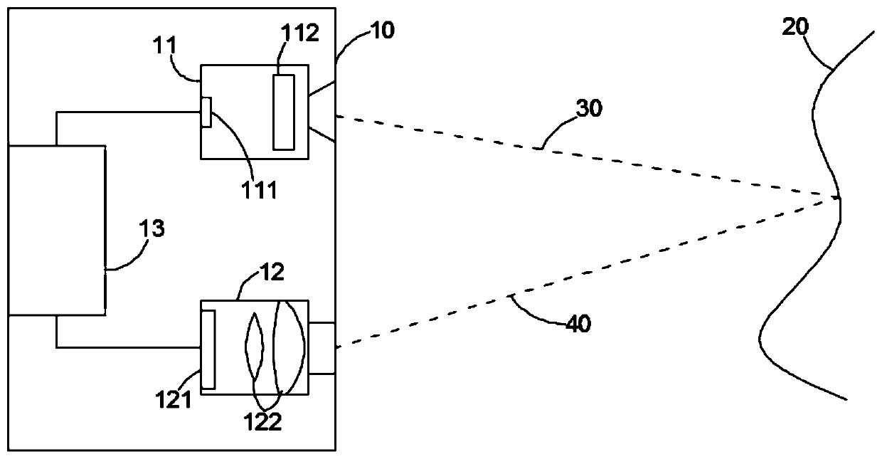
The invention discloses a system and method for time-coded time-of-flight distance measurement. The system includes a transmitter, a collector and a processing circuit; the transmitter is configured to transmit an optical signal pulse string having dual random time codes; the pulse string includes N pulse groups transmitted in the form of the second random time code, wherein the pulse groups include n pulses transmitted in the form of the first random time code; the collector is configured to collect photons in an optical signal pulse string reflected back by an object; the processing circuitis connected with the transmitter and the collector and is configured to count the photons to form N pulse group periodic single-photon counting time sequence strings; and a histogram is drawn based on the first random time code and the N pulse group periodic single-photon counting time sequence strings. With the system and the method adopted, the transmitter is allowed to transmit the pulse strings with a pulse period far shorter than the maximum time-of-flight corresponding to a maximum measurement range, so that a frame rate can be improved to a great extent.

Description

technical field [0001] The invention relates to the field of computer technology, in particular to a system and method for time-coded time flight distance measurement. Background technique [0002] Time of flight (TOF) method calculates the distance of objects by measuring the flight time of light beams in space. Due to its advantages of high precision and large measurement range, it is widely used in consumer electronics, unmanned vehicles, AR / VR and other fields. [0003] Distance measurement systems based on time-of-flight principles, such as time-of-flight depth cameras and lidar systems, often include a light source transmitter and a receiver. Calculate the distance of the object by calculating the time required for the light beam to be reflected and received. When using the direct time-of-flight method for measurement, the transmitter emits a pulsed beam to the target, and the pulsed beam is emitted at a certain frequency. The time interval (pulse period) between ad...

Claims


Application Information

Patent Timeline
Patent Type & Authority Applications(China)
IPC IPC(8): G01S7/486G01S17/10
CPCG01S7/4861G01S7/4865
Inventor 朱亮何燃王瑞闫敏
Owner ORADAR TECH CO LTD
Why Eureka
Try Eureka