Buried point event detection method and device, terminal equipment and medium

A detection method and point detection technology, which is applied in the computer field, can solve problems such as false positives, missed detection of buried point events, and the impact of function codes, and achieve the effects of improving detection efficiency, improving accuracy, and reducing intrusion

Pending Publication Date: 2019-12-31
BEIJING YOUZHUJU NETWORK TECH CO LTD
View PDF6 Cites 5 Cited by
  • Summary
  • Abstract
  • Description
  • Claims
  • Application Information

AI Technical Summary

Problems solved by technology

[0003] However, manual embedding is to directly combine the embedding code with the function code of the application during the programming process of the application, which is more intrusive to the application. If the embedding code is wrong, it will affect the function code of the application. Or, when the function code or buried point code needs to be updated, all corresponding updates are required, and the application can only be repaired by means of release or hot fix
[0004] Automatic burying and visual burying mainly use the burying tool program or visualization tool program to automatically complete the detection and reporting of burying events. The burying code is separated from the function code, so it is almost non-invasive, but because the tool automatically The added burying code is not closely combined with the function code, so the burying event will be missed or falsely reported, so the efficiency of burying event detection is low

Method used


Image

  • Buried point event detection method and device, terminal equipment and medium
  • Buried point event detection method and device, terminal equipment and medium
  • Buried point event detection method and device, terminal equipment and medium

Examples


Embodiment 1

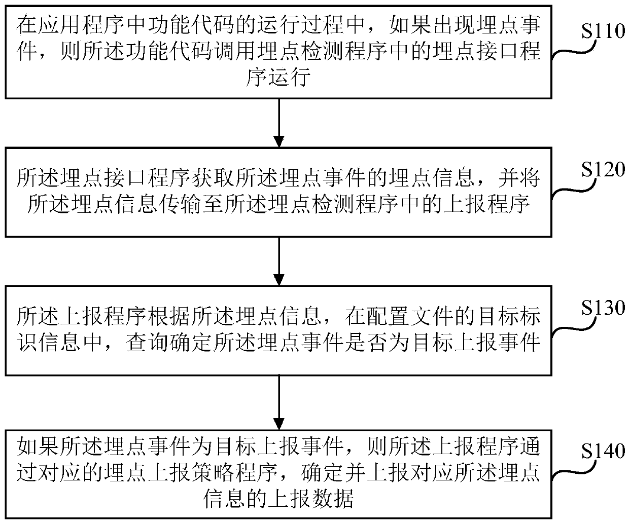
[0027] figure 1 It is a schematic flowchart of a method for detecting a buried point event provided by Embodiment 1 of the present disclosure. This method is applicable to the detection of a buried point event. Specifically, the method is applicable to the detection of buried points generated in an application program The event is detected. The method can be performed by a device for detecting buried point events, wherein the device can be implemented by software and / or hardware, and is generally integrated on a terminal device. In this embodiment, the terminal device includes but is not limited to: a mobile phone, a computer or a personal digital Assistant and other equipment.

[0028] Existing solutions for setting burying points in applications include manual burying, automatic burying and visual burying.

[0029] Manual point burying requires developers to write corresponding codes for the terminal platform, and when the user interacts with the application, the user's pa...

Embodiment 2

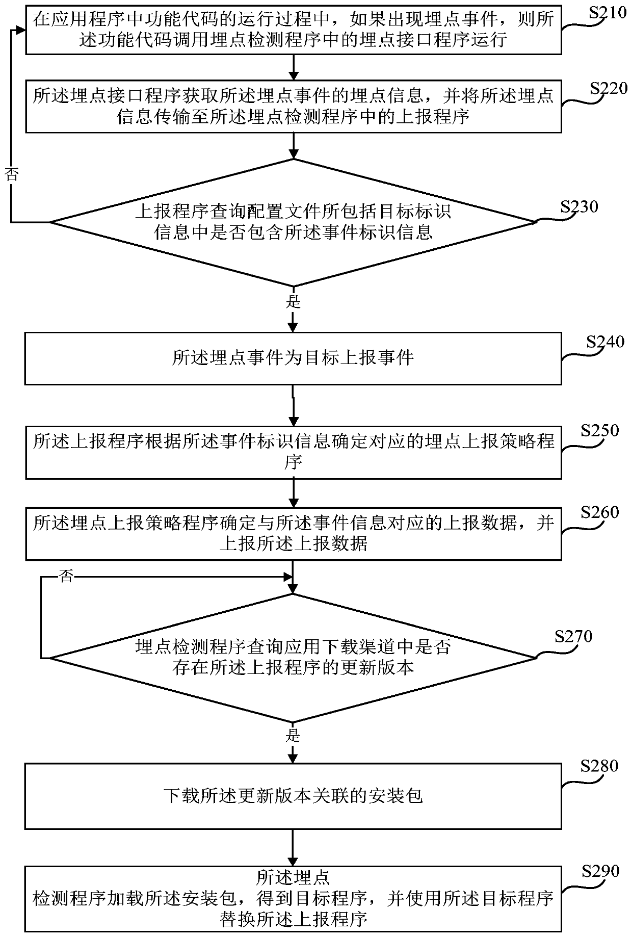
[0064] figure 2 It is a schematic flow chart of a method for detecting buried point events provided by Embodiment 2 of the present disclosure. Embodiment 2 is optimized on the basis of the foregoing embodiments. In this embodiment, the buried point information includes event identification information and event information, and the event information includes event name and event parameters.

[0065] Further, in this embodiment, the reporting program will query and determine whether the buried point event is a target reporting event in the target identification information of the configuration file according to the buried point information, and the optimization includes: the reporting program queries the configuration file Including whether the target identification information contains the event identification information;

[0066] If included, the buried point event is a target reporting event.

[0067] On the basis of the above-mentioned optimization, the reporting progra...

Embodiment 3

[0120] image 3 It is a schematic structural diagram of a detection device for a buried point event provided by Embodiment 3 of the present disclosure. The device is applicable to the detection of a buried point event. Specifically, the method is applicable to the detection of a buried point event generated in an application program. The event is detected. Wherein the device can be realized by software and / or hardware, and generally integrated on the terminal equipment.

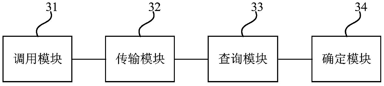
[0121] Such as image 3 As shown, the device includes: a call module 31, a transmission module 32, a query module 33 and a determination module 34;

[0122] Wherein, the calling module 31 is used for running the function code in the application program, if a buried point event occurs, the function code calls the buried point interface program in the buried point detection program to run;

[0123] The transmission module 32 is used for the buried point interface program to obtain the buried point informatio...


PUM


Abstract

The invention discloses a buried point event detection method and device, terminal equipment and a medium. The method comprises the steps that in the running process of a function code in an application program, if a burying point event occurs, the function code calls a burying point interface program in a burying point detection program to run; the buried point interface program acquires buried point information of the buried point event and transmits the buried point information to a reporting program in the buried point detection program; the reporting program queries and determines whetherthe burying point event is a target reporting event in target identification information of a configuration file according to the burying point information; and if the burying point event is a targetreporting event, the reporting program determines and reports reporting data corresponding to the burying point information through a corresponding burying point reporting strategy program. By utilizing the method, the invasiveness to the function code of the application program can be reduced, and the detection efficiency of the burying point event is improved.

Description

technical field [0001] Embodiments of the present disclosure relate to the field of computer technology, and in particular, to a detection method, device, terminal device, and medium for a buried point event. Background technique [0002] During the operation of the application program in the terminal device, it is often necessary to report the user's behavior data, that is, the tracking point. The common user behavior data detected by the buried point include click, display, entering a new page, and the length of time spent on the page. Existing solutions for setting tracking points in applications include manual tracking, automated tracking, and visual tracking. The main method is to add tracking codes in applications to detect user behavior data. [0003] However, manual embedding is to directly combine the embedding code with the function code of the application during the programming process of the application, which is more intrusive to the application. If the embeddi...

Claims


Application Information

Patent Timeline
Patent Type & Authority Applications(China)
IPC IPC(8): G06F11/36G06F8/61
CPCG06F11/3604G06F8/61
Inventor 不公告发明人
Owner BEIJING YOUZHUJU NETWORK TECH CO LTD
Why Eureka
Try Eureka