

Tail gas emission control method for fuel cell hydrogen recovery system
An exhaust emission and fuel cell technology, which is applied to fuel cells, electrical components, circuits, etc., can solve the problems of reduced output power capacity, neglect of the influence of nitrogen and hydrogen concentration, and fuel cell performance degradation, etc., to reduce hydrogen loss, The effect of low loss and low hydrogen concentration
Active Publication Date: 2019-12-31
上海氢尚新能源科技有限公司
View PDF5 Cites 4 Cited by
- Summary
- Abstract
- Description
- Claims
- Application Information
AI Technical Summary
Problems solved by technology
However, although this patent considers the hydrogen recovery of the hydrogen circuit and the external discharge of water in the buffer container, it does not consider the influence of nitrogen on the concentration of hydrogen.
In fact, in a proton exchange membrane fuel cell, if the cathode gas is ai
Method used
View moreImage
Smart ImageViewing Examples

Examples
Example Embodiment
[0038] Example 1:
Login to View More PUM
 Abstract
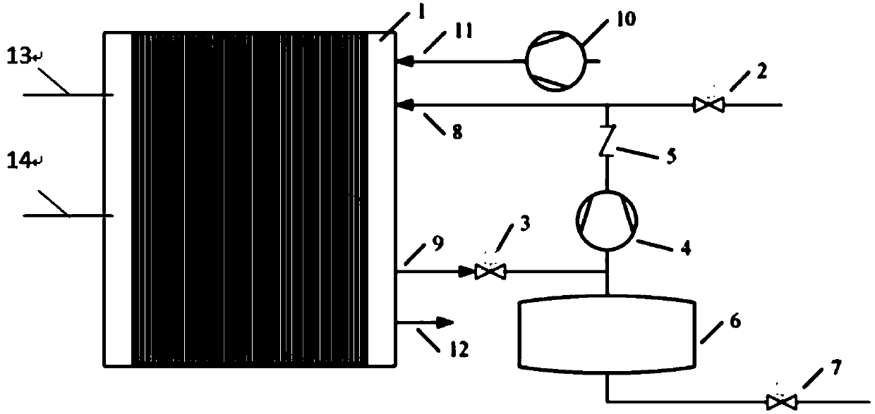
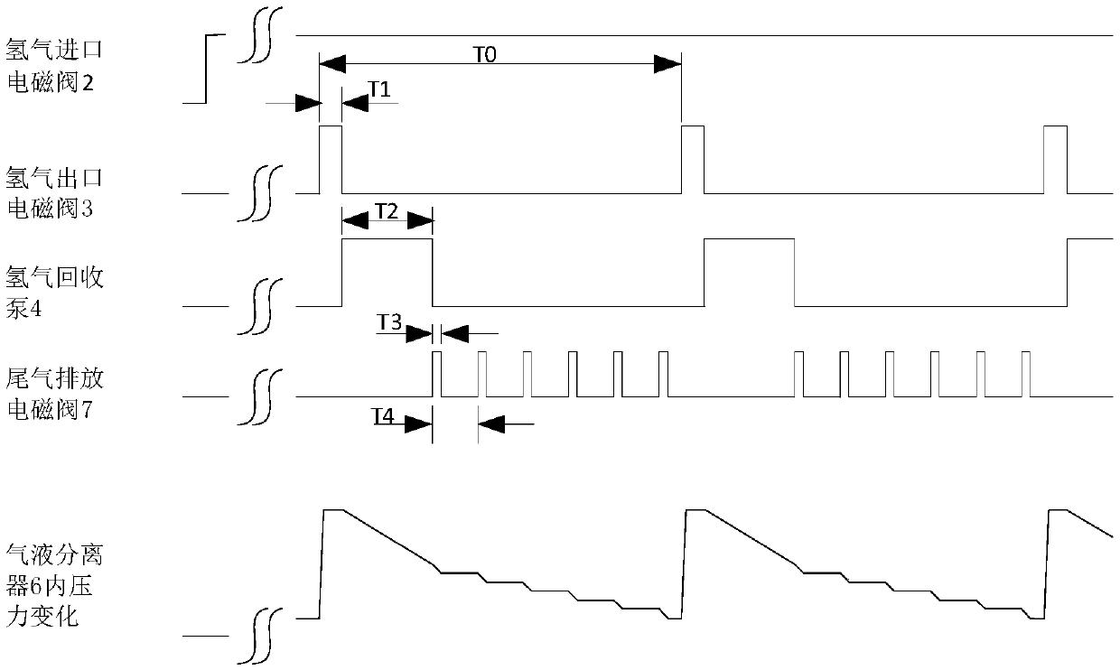
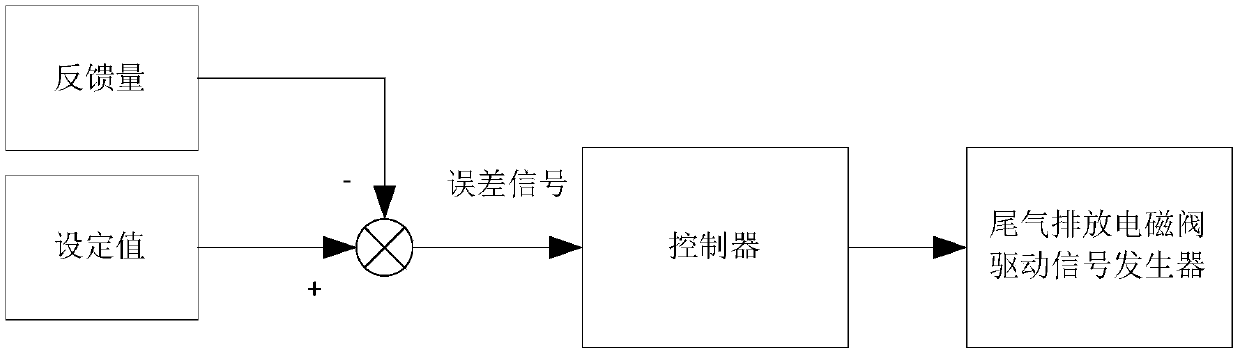
The invention relates to a tail gas emission control method for a fuel cell hydrogen recovery system, which comprises the following steps of: 1) opening a hydrogen inlet electromagnetic valve, keepinga hydrogen inlet pipeline open, simultaneously keeping a hydrogen outlet electromagnetic valve, a one-way stop valve and a tail gas emission electromagnetic valve closed, and enabling a stack to start reaction, 2) temporarily opening the hydrogen outlet electromagnetic valve and then closing the hydrogen outlet electromagnetic valve at the beginning of a control period, purging the tail gas withwater into a gas-liquid separator, at the moment, opening a hydrogen recovery pump and a one-way stop valve to recover hydrogen in the gas-liquid separator, and returning the recovered hydrogen into ahydrogen inlet pipeline for mixing, and 3) closing the hydrogen recovery pump and the one-way stop valve, and controlling the tail gas discharge electromagnetic valve to discharge the tail gas by thecontroller in a multi-time intermittent opening manner within the time when the hydrogen outlet electromagnetic valve, the hydrogen recovery pump and the one-way stop valve are all closed until the hydrogen outlet electromagnetic valve is opened in the next control period. Compared with the prior art, the method has the advantages of high efficiency, low hydrogen tail gas emission concentration and the like.
Description
technical field [0001] The invention relates to the field of fuel cell control, in particular to a tail gas emission control method of a fuel cell hydrogen recovery system. Background technique [0002] As a new type of environmentally friendly power generation product, fuel cells have the advantages of no noise, no pollution, small size, long life, high energy conversion rate, easy maintenance and low cost. [0003] An electrochemical fuel cell is a device that converts hydrogen and oxidants into electrical energy and reaction products. In a proton exchange membrane fuel cell using hydrogen as fuel and air containing oxygen as oxidant (or pure oxygen as oxidant), the catalytic electrochemical reaction of fuel hydrogen in the anode region produces positive hydrogen ions (or protons). The proton exchange membrane facilitates the migration of positive hydrogen ions from the anode region to the cathode region. In addition, the proton exchange membrane separates the hydrogen-c...
Claims
Login to View More Application Information
Patent Timeline
 IPC IPC(8): H01M8/04119H01M8/0662
CPCH01M8/0662H01M8/04119Y02E60/50
Inventor胡磊亚努士高勇
Owner上海氢尚新能源科技有限公司