Electric integrated operating device for J-shaped wire clamp

An operating device and wire clip technology, which is applied to the coupling device, the parts of the connecting device, and the connection/disconnection of the connecting device, etc., can solve the problems of danger, unstable clamping force of the operating device, cumbersome operation process, etc. The effect of simplicity, shortening work time and improving work efficiency

Active Publication Date: 2019-12-31
国网浙江省电力有限公司桐乡市供电公司
View PDF7 Cites 9 Cited by
  • Summary
  • Abstract
  • Description
  • Claims
  • Application Information

AI Technical Summary

Problems solved by technology

[0004] In order to overcome the cumbersome and dangerous operation process in the prior art, and the unstable clamping force of the operating device, the present invention provides an electric inte

Method used


Image

  • Electric integrated operating device for J-shaped wire clamp
  • Electric integrated operating device for J-shaped wire clamp
  • Electric integrated operating device for J-shaped wire clamp

Examples


Embodiment 1

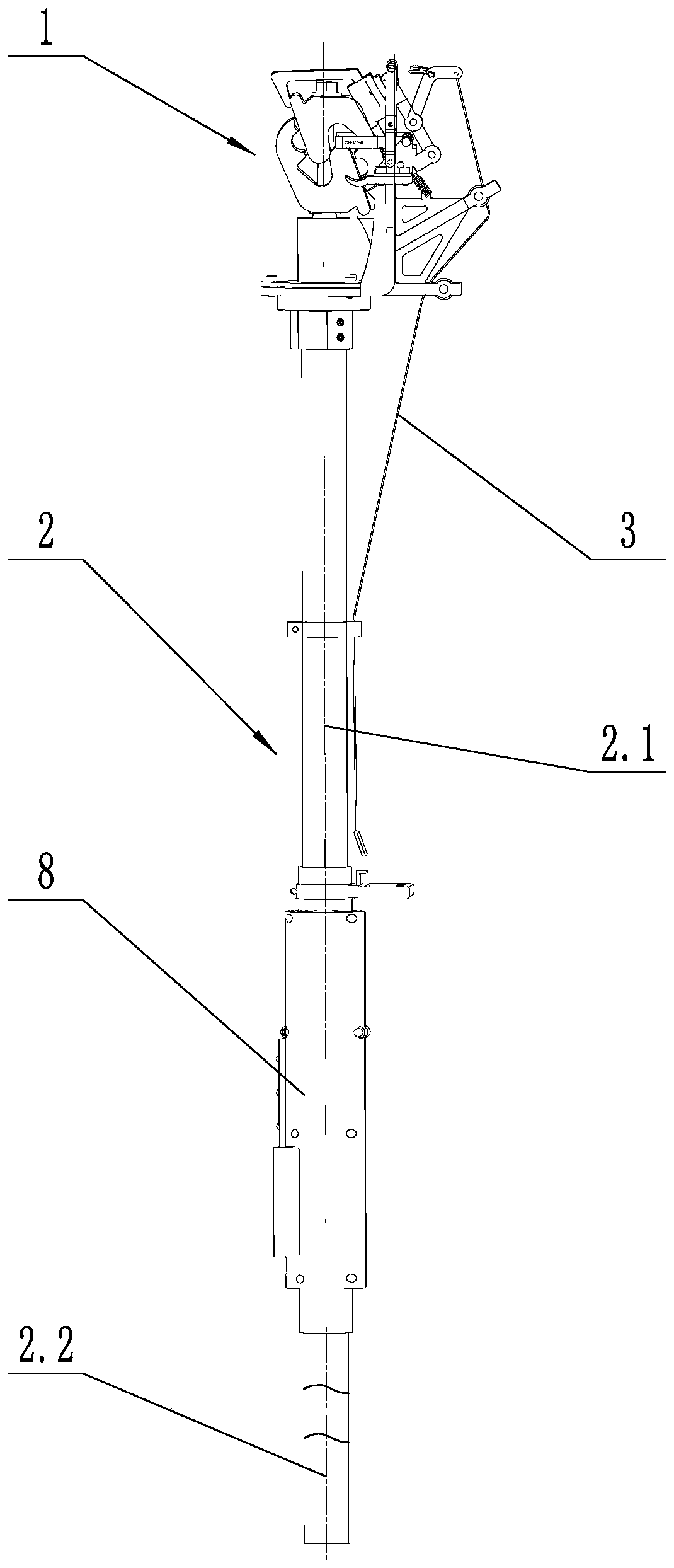
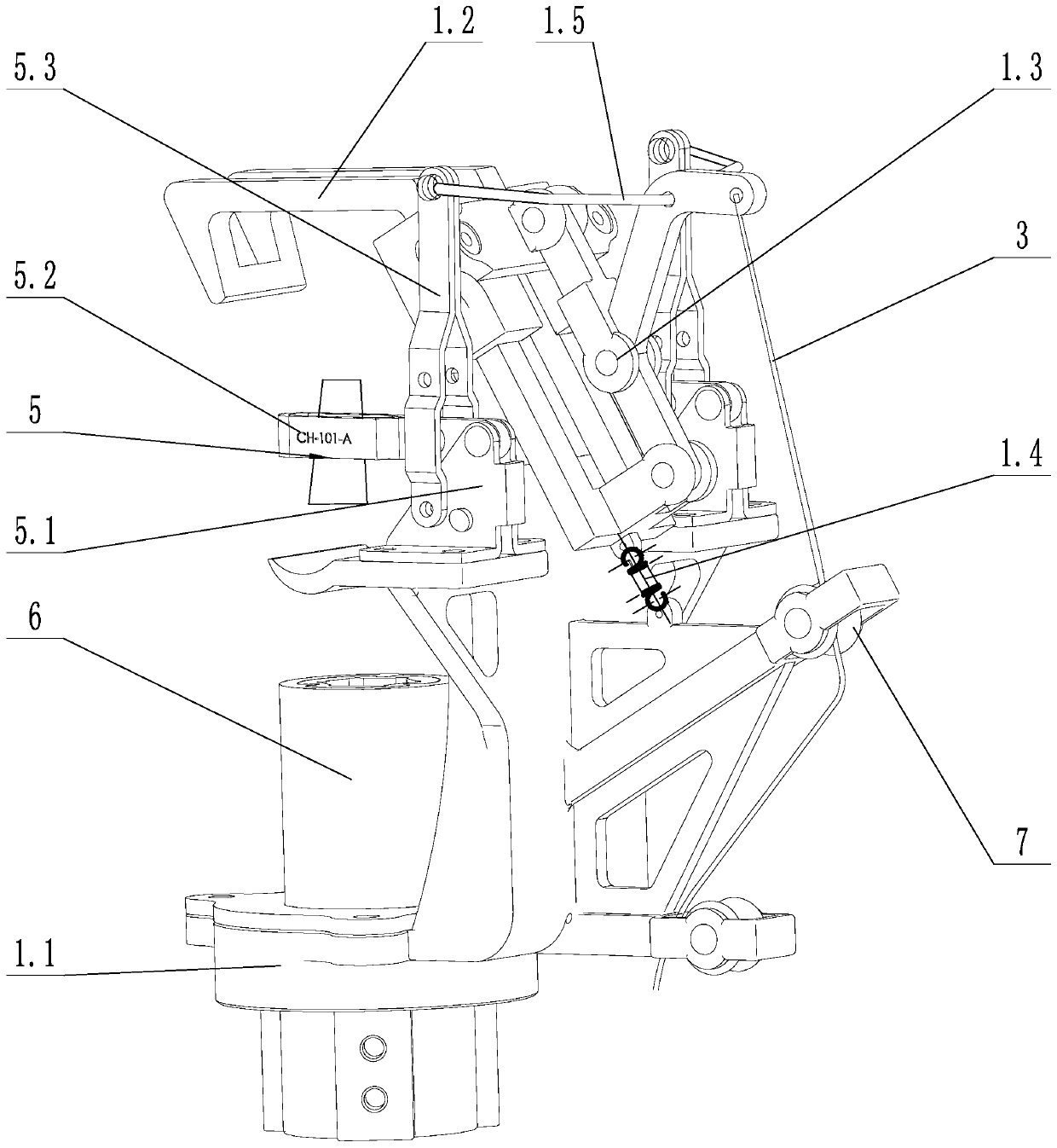
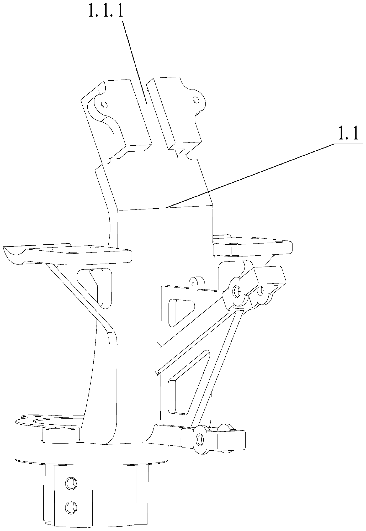
[0032] Such as figure 1 As shown, a J-type wire clamp electric integrated operating device includes a clamping assembly 1 and an insulating rod 2; as figure 2 , image 3 with Figure 4 As shown, the clamping assembly 1 includes a main frame 1.1, a slide bar chuck 1.2 for clamping a J-shaped clamp, a linkage mechanism 1.3 and a first telescopic spring 1.4, and the main frame 1.1 is provided with a chute 1.1.1, The guide wheel 7 and the nut fastening device 6, the slide bar chuck 1.2 includes a slide bar part 1.2.1 and a chuck part 1.2.2, and the slide bar part 1.2.1 is adapted and slidably connected to the chute 1.1.1; the first One end of the telescopic spring 1.4 is connected with the main body frame 1.1, and the other end of the first telescopic spring 1.4 is connected with the slider chuck 1.2; the link mechanism 1.3 includes a first connecting rod 1.3.1 and a second connecting rod 1.3. The lever 1.3.2 includes a locking lever 1.3.2.1 and an unlocking lever 1.3.2.2 conn...

Embodiment 2

[0037] Such as figure 2 As shown, on the basis of implementation 1, the main frame 1.1 is provided with a quick wire clamp 5, and the quick wire clamp 5 includes a base 5.1, a clamping piece 5.2 and a locking piece 5.3 for locking the clamping piece 5.2; The base 5.1 is arranged on both sides of the slider clamp 1.2, one end of the locking piece 5.3 is hinged with the base 5.1, the other end of the locking piece 5.3 is connected with the unlocking lever 1.3.2.2 through the connecting piece 1.5, and the locking piece 5.3 The direction of rotation is parallel to the direction of rotation of the locking lever 1.3.2.1. .

[0038] The above connecting piece 1.5 is indirectly fixed to the main frame 1.1 by connecting with the quick wire clamp 5. When the clamping piece 5.2 clamps the cable together with the main frame 1.1, the locking piece 5.35..3 is far away from the unlocking lever 1.3.2.2, At this time, the unlocking pull cord 3 is pulled, and the unlocking lever 1.3.2.2 rota...


PUM


Abstract

The invention discloses an electric integrated operating device for a J-shaped wire clamp. The electric integrated operating device comprises a clamping assembly and an insulating rod. The clamping assembly comprises a main body frame, a sliding rod chuck, a connecting rod mechanism and a first telescopic spring. The sliding rod chuck is in sliding connection with the main body frame. The connecting rod mechanism comprises a first connecting rod and a second connecting rod. The second connecting rod comprises a locking rod and an unlocking rod which are connected with each other. A corner is arranged between the locking rod and the unlocking rod; the joint of the locking rod and the unlocking rod is hinged to the first connecting rod; the other end of the first connecting rod is hinged tothe main body frame; the other end of the locking rod is hinged to the sliding rod chuck; the unlocking rod is provided with an unlocking pull rope and a rotating hole, wherein the rotating hole is formed between the unlocking pull rope and the locking rod, and the rotating hole is internally provided with a connecting piece; and one end of the connecting piece is connected with the main body frame. The electric integrated operating device for the J-shaped wire clamp is simple to operate; the clamping state of the clamping assembly is stable and reliable; and unlocking is convenient and rapid.

Description

technical field [0001] The invention relates to the technical field of electric equipment maintenance tools, in particular to an electric integrated operating device for a J-shaped wire clamp. Background technique [0002] J-shaped clamps are mostly used for power connection equipment in power transmission and distribution systems. In the process of drainage of high-voltage power grid lines, live work is often required in order not to affect normal power supply. Therefore, a set of fast, safe, efficient and accurate clamps is researched and designed. The J-type clamp operating device for distribution line drainage is particularly important. At present, most of the wire clip operating devices are manually operated, the operation process is cumbersome and dangerous, the uncertain factors of the operation are too large, and the stability of the wiring is not high. Therefore, it is necessary to develop a safe, reliable, efficient and lightweight, and has a certain Automated J-s...

Claims


Application Information

Patent Timeline
IPC IPC(8): H01R11/15H01R13/633H01R13/627H01R43/26
CPCH01R11/15H01R13/627H01R13/633H01R43/26
Inventor 徐劲榕钱栋孙锦凡张李洵蒋孜律濮少羽李超钟正阳
Owner 国网浙江省电力有限公司桐乡市供电公司
Why Eureka
Try Eureka