Disassembling-and-assembling-facilitating anti-theft power cabinet

A technology that facilitates disassembly and assembly of power cabinets. It is applied in the direction of substation/switchgear cooling/ventilation, electrical components, and locks for non-mechanical transmission operations. It can solve unfavorable power cabinet maintenance, disassembly and assembly problems, and disassembly and maintenance. Convenience and other issues, to achieve the effect of anti-theft, quick dismantling, and beneficial to secondary use

Active Publication Date: 2019-12-31
苏州笑聪电气设备有限公司
View PDF14 Cites 1 Cited by
  • Summary
  • Abstract
  • Description
  • Claims
  • Application Information

AI Technical Summary

Problems solved by technology

[0002] The power cabinet is the final equipment in the power distribution system. It is usually installed outdoors away from the power supply center. If the electrical components inside the power cabinet are damaged, it is generally necessary to open the box when maintaining the electrical components inside the power cabinet. The maintenance of the door, but due to the design characteristics of the cabinet, it is generally very difficult to maintain, unless the entire cabinet is disassembled, but this disassembly is time-consuming and laborious, which is not conducive to the maintenance of the power cabinet
In addition, power cabinets often have theft accidents, which seriously affect the normal production and power supply. The stolen components in the power cabinet not only bring economic losses to the power department, but also cause a great waste of time and manpower.
[0003] Chinese patent CN201811217498.1 discloses a power cabinet for factory buildings that is easy to install and maintain, including: an installation bottom support, the bottom of which is arranged in an underground installation groove, and A hydraulic column is installed, and a bottom plate of the power cabinet is installed above the hydraulic column. Several heat dissipation through holes are opened in the center of the bottom plate of the power cabinet. A cooling fan installed symmetrically up and down is arranged between the hydraulic columns. The power cabinet The outer casing is connected above the bottom plate; the internal space of the power cabinet body is divided into several small spaces by layered partitions, which greatly utilizes the space, and at the same time facilitates operation and maintenance during the installation process and improves the installability of the device. The installation and maintenance method requires the use of large-scale equipment, and the disassembly and maintenance are not very convenient
However, the early warning will cause a time delay, and the personnel who steal the power cabinet often have corresponding measures to deal with it, and the effect is not good
[0004] Conventional power cabinets in the prior art are usually made of sheet metal. The electric cabinet body is pre-processed to form a rectangular three-dimensional structure, and then the doors of the power cabinet are installed through hinges. Anti-theft locks are installed between the doors of the power cabinet. The characteristics of the anti-theft lock exposed and the preformed manufacturing of the power cabinet body, the existing lock technology is getting more and more advanced, the anti-theft lock exposed will have a certain impact on safety, and the preformed manufacturing of the power cabinet body will cause the power cabinet body to be too large It is inconvenient to transport, and it brings trouble to disassembly to a certain extent

Method used


Image

  • Disassembling-and-assembling-facilitating anti-theft power cabinet
  • Disassembling-and-assembling-facilitating anti-theft power cabinet
  • Disassembling-and-assembling-facilitating anti-theft power cabinet

Examples


Embodiment Construction

[0032] The present invention will be further described in detail below in conjunction with the accompanying drawings, so that those skilled in the art can implement it with reference to the description.

[0033] It should be understood that terms such as "having", "comprising" and "including" used herein do not exclude the presence or addition of one or more other elements or combinations thereof.

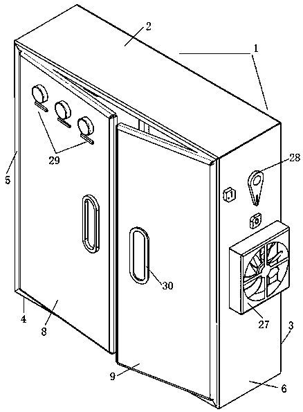
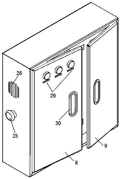
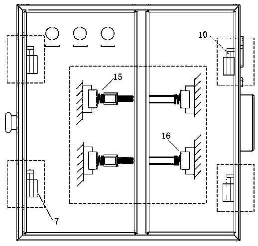
[0034] Conventional power cabinets in the prior art are usually made of sheet metal. The cabinet body of the power cabinet is pre-processed to form a rectangular three-dimensional structure, and then the doors of the power cabinet are installed through hinges. Anti-theft locks are installed between the doors of the power cabinet. The anti-theft lock is exposed and the power cabinet is preformed. The existing lock technology is getting more and more advanced. The anti-theft lock will have a certain impact on safety. The power cabinet preformed manufacturing will cause the power cabin...


PUM


Abstract

The invention discloses a disassembling-and-assembling-facilitating anti-theft power cabinet comprising a power cabinet body which is composed of a top plate, a back plate, a bottom plate, a left plate and a right plate. The two sides of the front part of the power cabinet body are symmetrically provided with two sets of sockets fixed on the edge of the left plate and the edge of the right plate.A left cabinet door match with the power cabinet body is rotatably installed on the left side plate through the socket. A right cabinet door matched with the left cabinet door is rotatably installed on the right side plate through the socket. A transmission piece of a rectangular frame structure is rotatably installed on the inner wall of the left side plate and the inner wall of the right side plate respectively through a rotating shaft base. Matching eccentric wheels are rotatably installed around the transmission piece through the opened transmission holes. The eccentric wheels are connected with the rotating shaft base through a rotating shaft. The outer end surface of the eccentric wheels is connected with threaded connecting columns coaxial with the rotating shaft, and a magnetic locking piece is installed between one eccentric wheel and the rotating shaft base. The power cabinet can be quickly spliced to realize overall linkage disassembling and assembling so as to facilitate transportation, and the anti-theft effect is realized through the non-exposed anti-theft lock.

Description

technical field [0001] The invention relates to the technical field of power cabinets, in particular to an anti-theft power cabinet that is easy to assemble and disassemble. Background technique [0002] The power cabinet is the final equipment in the power distribution system. It is usually installed outdoors away from the power supply center. If the electrical components inside the power cabinet are damaged, it is generally necessary to open the box when maintaining the electrical components inside the power cabinet. The door can be repaired, but due to the design characteristics of the cabinet, it is generally very difficult to maintain, unless the entire cabinet is disassembled, but this disassembly is time-consuming and laborious, which is not conducive to the maintenance of the power cabinet. In addition, power cabinets often have theft accidents, which seriously affect the normal production and power supply. The parts in the stolen power cabinets not only bring econom...

Claims


Application Information

Patent Timeline
Patent Type & Authority Applications(China)
IPC IPC(8): H02B1/30H02B1/56E05B65/02E05B63/14E05B47/00E05B19/00
CPCE05B47/004E05B47/0045E05B63/143E05B65/025H02B1/30H02B1/565
Inventor 王朋
Owner 苏州笑聪电气设备有限公司
Why Eureka
Try Eureka