Axial magnetic field reverse salient pole permanent magnet synchronous motor

A technology of permanent magnet synchronous motor and axial magnetic field, which is applied to synchronous motors with stationary armatures and rotating magnets, motors, magnetic circuits, etc., can solve problems such as increasing inverter capacity and reducing drive system efficiency The effect of high power density and reliability, high structural strength and small cogging torque

Active Publication Date: 2019-12-31
HARBIN INST OF TECH
View PDF16 Cites 6 Cited by
  • Summary
  • Abstract
  • Description
  • Claims
  • Application Information

AI Technical Summary

Problems solved by technology

[0016] The present invention is to solve the problem that the capacity of the inverter will be increased and the efficiency of the drive system will be reduced when the traditional permanent magnet synchronous motor operates in a wide speed range. Now it provides three structures of axial magnetic field anti-saliency permanent magnets synchronous motor

Method used


Image

  • Axial magnetic field reverse salient pole permanent magnet synchronous motor
  • Axial magnetic field reverse salient pole permanent magnet synchronous motor
  • Axial magnetic field reverse salient pole permanent magnet synchronous motor

Examples


specific Embodiment approach 1

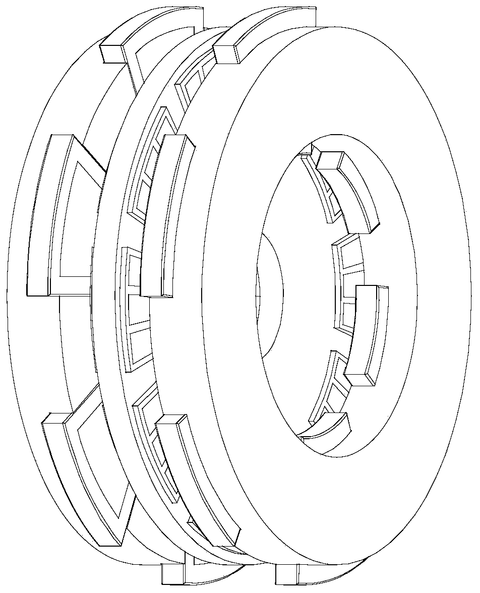
[0057] Specific implementation mode one: refer to Figure 5 , 6 , 7, 9 and 10 specifically describe this embodiment, the axial magnetic field anti-salient pole permanent magnet synchronous motor described in this embodiment includes: a rotor and two stators, the rotor and the two stators are coaxially arranged, and the rotor is located at two There is an air gap between the two stators, and between the rotor and the two stators.

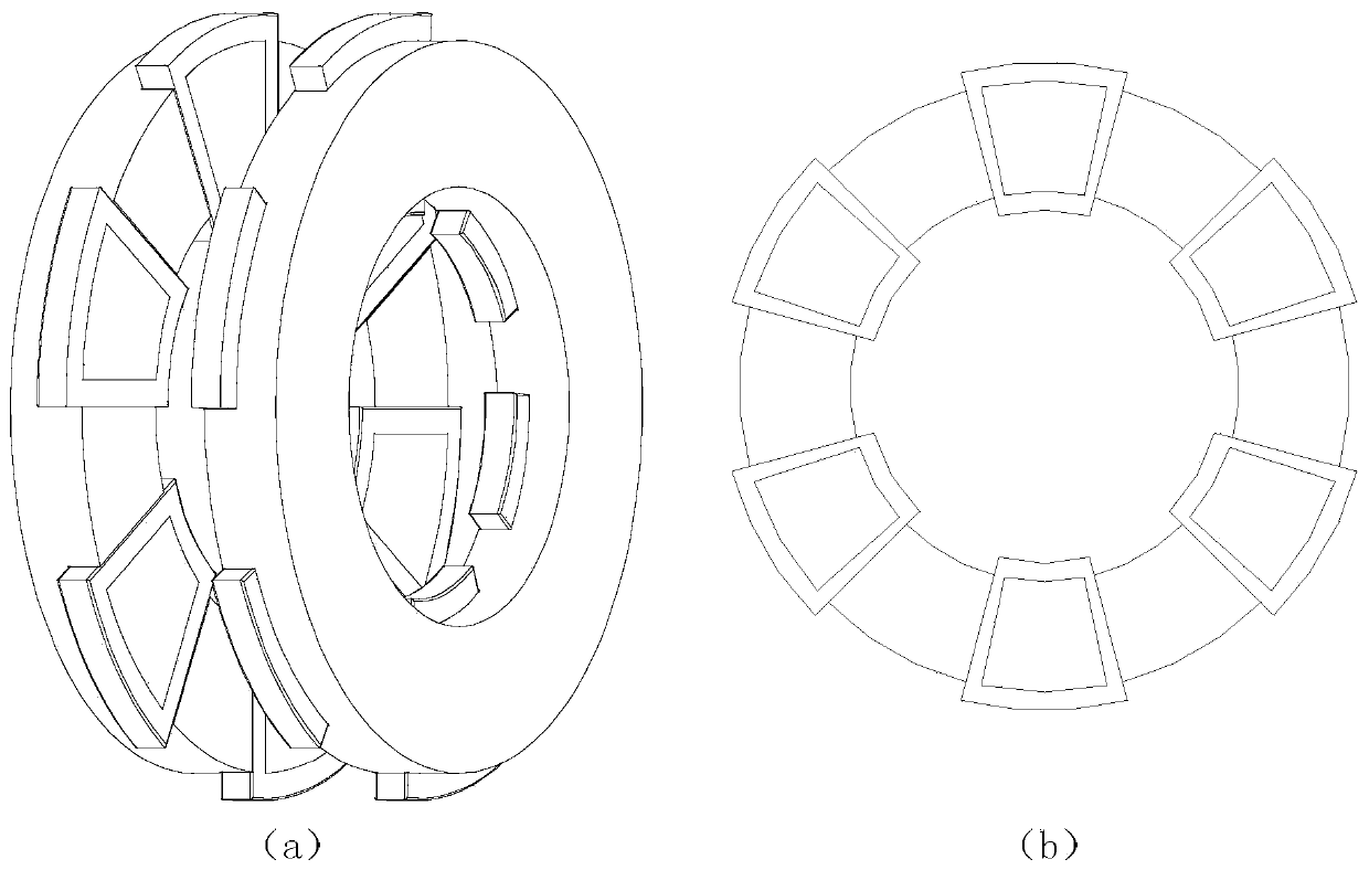
[0058] The rotor includes a circular base plate, on which there are 2p circular sector-shaped magnetic pole unit embedding through holes uniformly arranged along its circumference, and the narrow sides of the ring sector are all facing the center of the base plate, and each magnetic pole A magnetic pole unit is embedded inside the unit embedding through hole,

[0059] The magnetic pole unit includes a magnetizer and 2k+1 permanent magnets, the outer contour of the magnetizer is the same as the inner contour of the through hole for embedding the mag...

specific Embodiment approach 2

[0061] Specific implementation mode two: refer to Figure 5 , 6 , 7, 8 and 10 specifically illustrate this embodiment, the axial magnetic field anti-salient pole permanent magnet synchronous motor described in this embodiment includes: a rotor and two stators, the rotor and the two stators are coaxially arranged, and the rotor is located at two There is an air gap between the two stators, and between the rotor and the two stators.

[0062] The rotor includes a circular base plate, on which there are 2p circular sector-shaped magnetic pole unit embedding through holes uniformly arranged along its circumference, and the narrow sides of the ring sector are all facing the center of the base plate, and each magnetic pole A magnetic pole unit is embedded inside the unit embedding through hole,

[0063] The magnetic pole unit includes a magnetizer and 2n pieces of permanent magnets. The outer contour of the magnetizer is the same as the inner contour of the through hole for embeddi...

specific Embodiment approach 3

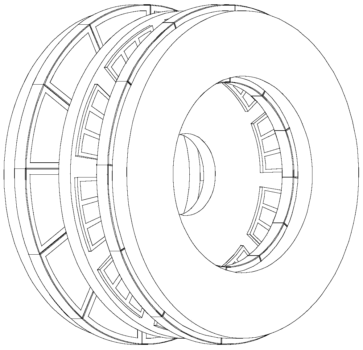
[0065] Specific implementation mode three: refer to Figure 7 , 9 , 10, 11 and 12 specifically describe this embodiment, the axial magnetic field anti-salient pole permanent magnet synchronous motor described in this embodiment includes: a rotor and two stators, the rotor and the two stators are coaxially arranged, and the rotor is located at two There is an air gap between the two stators, and between the rotor and the two stators.

[0066] The rotor includes a ring-shaped base plate, and 2p grooves are evenly opened on the circumference of the base plate to the direction of its inner ring, and each groove is embedded with a magnetic pole unit.

[0067] The magnetic pole unit includes a magnet guide and 2k+1 permanent magnets, the magnet guide is in the shape of a ring sector, and the magnet guide is evenly opened with 2k+1 permanent magnet embedding holes along its circumference, and the 2k+1 permanent magnets are respectively embedded in the 2k+1 permanent magnets are emb...


PUM


Abstract

The invention provides an axial magnetic field reverse salient pole permanent magnet synchronous motor, relates to the field of permanent magnet synchronous motors and aims to solve problems that thecapacity of an inverter is increased and efficiency of a driving system is reduced when a traditional permanent magnet synchronous motor operates in a relatively wide speed range. The axial magnetic field reverse salient pole permanent magnet synchronous motor is composed of two stators, a rotor and two air gaps, wherein each stator is composed of a stator iron core and a stator winding, and the rotor is mainly composed of a basal disc and magnetic pole units. The axial magnetic field reverse salient pole permanent magnet synchronous motor is wide in constant power flux weakening speed regulation range, high in structural strength of the rotor, small in positioning torque of the motor and high in efficiency, power density and reliability and has good application prospects in the fields ofelectric vehicle driving systems, electric spindle systems, variable-speed power generation and the like.

Description

technical field [0001] The invention belongs to the field of motors, in particular to a permanent magnet synchronous motor. Background technique [0002] Axial field permanent magnet motors, also known as disc permanent magnet motors, have attracted more and more attention due to their compact structure, high efficiency, and high power density. Axial field permanent magnet motors are especially suitable for applications requiring high torque density and compact space, such as electric vehicles, renewable energy systems, flywheel energy storage systems, and industrial equipment. [0003] Axial field permanent magnet motors have various structures, which can be divided into four types according to the number of stators and rotors and the relative positions of stators and rotors: single stator rotor structure, double stator intermediate rotor structure, double rotor intermediate stator structure and multi-disk structure. [0004] The traditional double stator intermediate roto...

Claims


Application Information

Patent Timeline
Patent Type & Authority Applications(China)
IPC IPC(8): H02K16/04H02K21/24H02K1/27H02K1/14H02K3/12
CPCH02K1/146H02K1/2793H02K3/12H02K16/04H02K21/24H02K2201/03H02K2213/03Y02T10/64
Inventor 寇宝泉赵晓坤杨小宝
Owner HARBIN INST OF TECH
Why Eureka
Try Eureka