Hand bag double-sided printing and folding device
A double-sided printing, handbag technology, applied in the directions of printing, printing machines, rotary printing machines, etc., can solve the problem that the production efficiency of handbags cannot meet customer requirements, and achieve the effect of ensuring stability and improving production efficiency.
- Summary
- Abstract
- Description
- Claims
- Application Information
AI Technical Summary
Problems solved by technology
Method used
Image
Examples
Embodiment 1
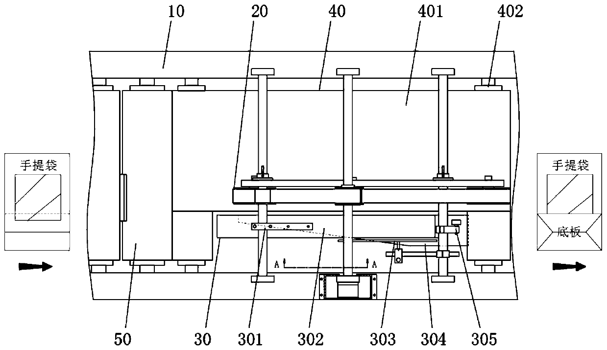
[0038] Embodiment one, with reference to figure 1 with image 3 , a handbag double-sided printing and folding device, including a frame body 10, a synchronous pressing assembly 20, a guide assembly 30, a transmission assembly 40 and a printing assembly 50, and the printing assembly 50 and the transmission assembly 50 are installed inside the frame body 10 from left to right Component 40, and the front end of the transmission component 40 is provided with a synchronous pressing component 20, and a guide component 30 is provided below;
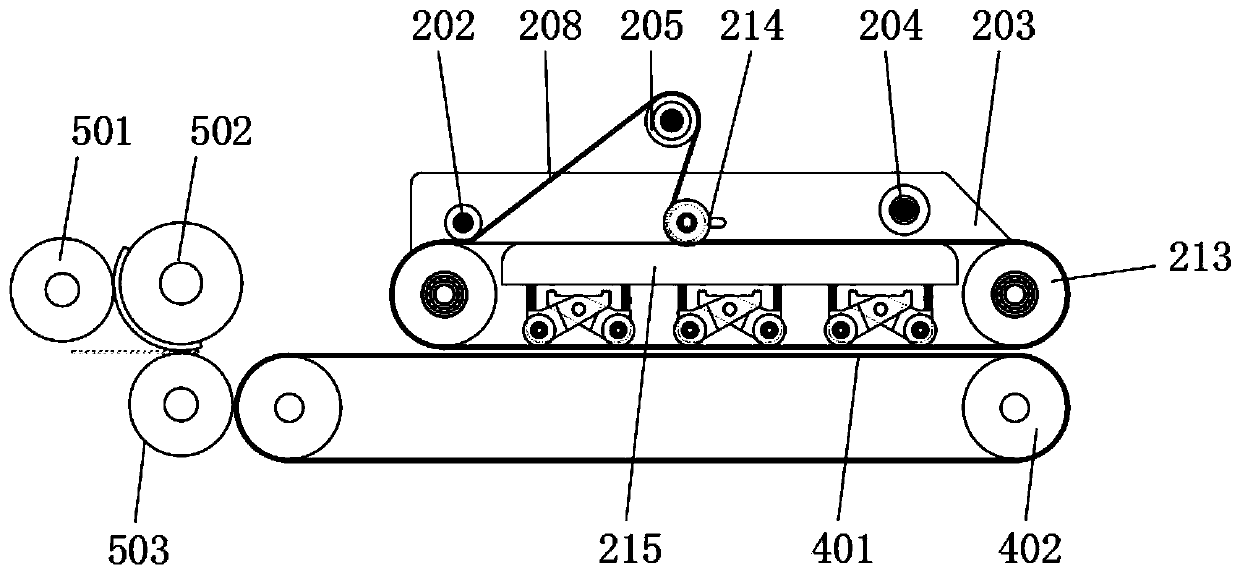
[0039] The printing assembly 50 includes an ink roller 501, a printing roller 502, and a pressure roller 503, and one end of the printing roller 502 is connected to a motor driving its rotation, and the ends of the printing roller 502, the ink roller 501, and the pressure roller 503 are connected through a gear transmission. ;
[0040] The upper surface of the handbag to be printed is completed by the printing assembly 50, conveyed and moved u...
Embodiment 2
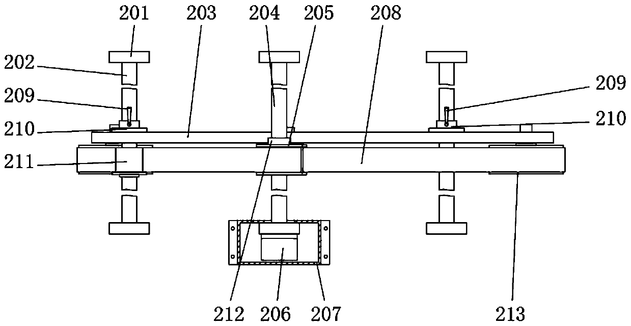
[0041] Embodiment two, refer to Figure 1-5 , The synchronous pressing assembly 20 includes a support vertical plate 201, a support shaft 202, a mounting plate 203, a drive shaft 204, a drive pulley 205, a drive motor 206, a protective cover 207, a timing belt 208, an adjustment handle 209, a connecting flange 210, Steering pulley 211, expansion sleeve 212, driven pulley 213, tension pulley 214, beam 215, spring 216, floating block 217, pressing wheel 218;
[0042]There are a plurality of support vertical plates 201, and the bottom ends of the plurality of support vertical plates 201 are fixedly connected to the surface of the frame body 10. Among them, a support shaft 202 and a drive shaft are erected between the upper and lower corresponding support vertical plates 201. 204, the mounting plate 203 is fixed on the support shaft 202 through the connection flange 210, wherein the connection flange 210 is provided with an adjustment handle 209, and the drive shaft 204 is fixed w...
Embodiment 3
[0045] Embodiment three, refer to figure 1 with Image 6 , guide assembly 30, first adjustment block 301, pressure plate 302, guide rod 303, guide plate 304, second adjustment block 305, connecting rod 306, vertical adjustment rod 307, horizontal adjustment rod 308, third adjustment block 309;
[0046] The first adjusting block 301, the second adjusting block 305 and the third adjusting block 309 are respectively fixed on the corresponding supporting shaft 202 by set screws, and a pressing plate 302 is suspended below the first adjusting block 301 through a connecting rod 306, and the pressing plate 302 The bottom is provided with guide plate 304, and the second adjustment block 305 is vertically connected with the third adjustment block 309 and the vertical adjustment rod 307 through the horizontal adjustment rod 308, and the vertical adjustment rod 307 lower end is welded with guide rod 303, and the third adjustment block The lower end of 309 is rotatably connected with a t...
PUM
 Abstract
Description
Claims
Application Information
 - R&D
- Intellectual Property
- Life Sciences
- Materials
- Tech Scout
- Unparalleled Data Quality
- Higher Quality Content
- 60% Fewer Hallucinations
Browse by: Latest US Patents, China's latest patents, Technical Efficacy Thesaurus, Application Domain, Technology Topic, Popular Technical Reports.
© 2025 PatSnap. All rights reserved.Legal|Privacy policy|Modern Slavery Act Transparency Statement|Sitemap|About US| Contact US: help@patsnap.com


