
Constant small-tension-path direct-unwinding and unwinding device and method thereof

A pay-off device and tension technology, which is applied in the field of constant small tension path direct release and pay-off device, can solve the problems affecting the tensile uniformity of the optical cable, inconsistent polyester yarn tension, and affecting the mechanical properties of the optical cable, etc., and achieve simplified constant tension control mode, improve the uniformity of tensile strength, and facilitate the effect of moving and exchanging

Active Publication Date: 2020-01-03
YANGTZE OPTICAL FIBRE & CABLE CO LTD +1
View PDF16 Cites 0 Cited by
  • Summary
  • Abstract
  • Description
  • Claims
  • Application Information

AI Technical Summary

Problems solved by technology

This pay-off method has the following problems: using constant torque for pay-off, during the pay-off process, as the pay-off proceeds, the diameter of the yarn cluster gradually decreases, so the tension of the pay-off will gradually increase, which makes the released yarn tight Inconsistencies lead to inconsistent tension of the polyester yarn in the length direction of the cable, and are prone to bifurcation and broken strands, resulting in hidden dangers of defective products, thereby affecting the tensile uniformity of the cable and affecting the mechanical properties of the cable

Method used

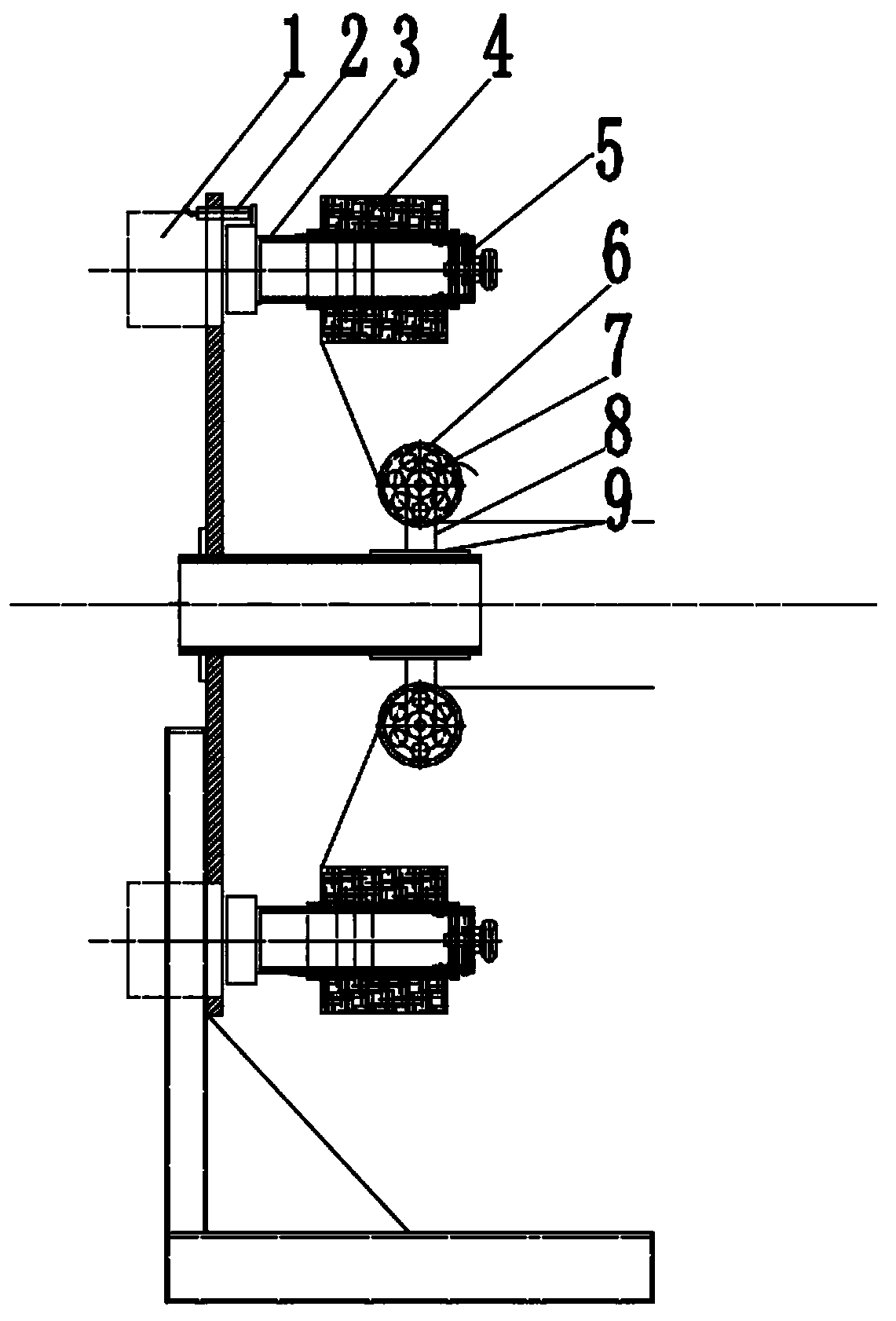

Image

  • Constant small-tension-path direct-unwinding and unwinding device and method thereof
  • Constant small-tension-path direct-unwinding and unwinding device and method thereof
  • Constant small-tension-path direct-unwinding and unwinding device and method thereof

Examples


Embodiment Construction

[0032] It should be understood that the specific embodiments described here are only used to explain the present invention, not to limit the present invention.

[0033] It should be noted that, in the description of the present invention, the terms "horizontal", "vertical", "upper", "lower", "front", "rear", "left", "right", "vertical", The orientation or positional relationship indicated by "horizontal", "top", "bottom", "inner", "outer", etc. is based on the orientation or positional relationship shown in the drawings, and is only for the convenience of describing the present invention and simplifying the description, and It is not to indicate or imply that the device or element referred to must have a particular orientation, be constructed in a particular orientation, or operate in a particular orientation, and thus should not be construed as limiting the invention. In addition, the terms "first", "second", etc. are used for descriptive purposes only, and should not be cons...


PUM


Abstract

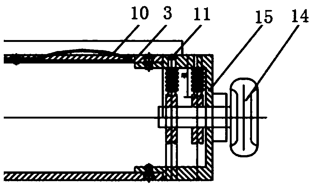
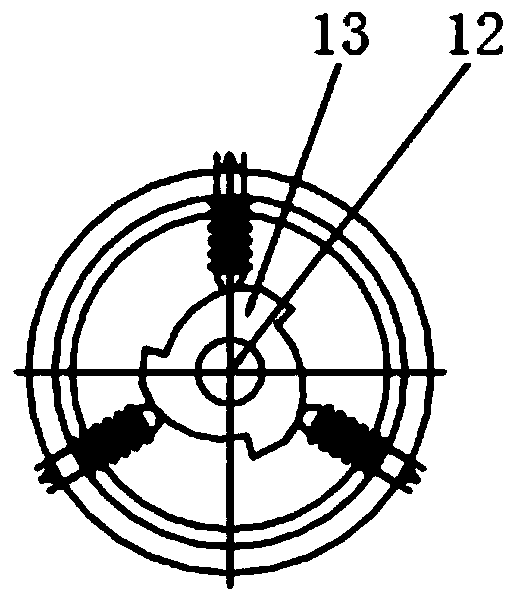
The invention discloses a constant small-tension-path direct-unwinding and unwinding device. The constant small-tension-path direct-unwinding and unwinding device comprises a base, a yarn installationcylinder, an magnetic remanence brake and a guide wheel, wherein the yarn installation cylinder and the guide wheel are installed on the base and can rotate on the base, the end part of the yarn installation cylinder is connected with the magnetic remanence brake, the guide wheel and the yarn installation cylinder are correspondingly fixed to a steering wheel speed measurement proximity switch and a installing cylinder speed measurement proximity switch, and the magnetic moment output by the magnetic remanence brake is reduced as the rotation speed of the yarn installation cylinder is increased; and the invention further provides a winding method of the constant-small-tension-path direct-unwinding and unwinding device. The constant-tension-path direct-unwinding and unwinding device and the method thereof can realize constant-tension control on the unwinding yarn.

Description

technical field [0001] The invention relates to the technical field of auxiliary equipment for optical cable production, in particular to a constant small tension path straight pay-off device and a method thereof. Background technique [0002] Part of the structural type of optical cable requires a large amount of aramid polyester yarn. Due to the use of yarn and its low tension, it is hoped that the number of guide wheels passing by during the unwinding process of aramid fiber should be as small as possible, so as to reduce the branching and broken strands of the yarn. The cable and broken yarn caused by the phenomenon. [0003] The tensile performance of the optical cable is mainly realized by the polyester yarn, and the polyester yarn needs to be pre-tensioned during the unwinding process to improve the tensile ability of the optical cable. At present, the implementation method of the process equipment is: the yarn cluster itself does not rotate, and is fixed on a suppor...

Claims


Application Information

Patent Timeline
Patent Type & Authority Applications(China)
IPC IPC(8): B65H59/04
CPCB65H59/043B65H2701/31
Inventor 李智刚吴斌盛黄杰陈锋
Owner YANGTZE OPTICAL FIBRE & CABLE CO LTD
Learn More