Mechanical damping passive pay-off unit

A pay-off device and mechanical damping technology, which is applied in the directions of transportation and packaging, delivery of filamentous materials, thin material handling, etc., can solve the problems that the cable is easy to move back and forth, affects the stability of the pay-off, and affects the work of the pay-off, etc. Achieve safe and convenient use, reduce friction and improve stability

Active Publication Date: 2020-01-03
NANJING INST OF RAILWAY TECH
View PDF15 Cites 13 Cited by
  • Summary
  • Abstract
  • Description
  • Claims
  • Application Information

AI Technical Summary

Problems solved by technology

[0002] With the continuous development of the economy, more and more places assume that the cable is used for power information transmission. In the cable laying work, a cable pay-off device is needed. The traditional cable pay-off device uses an I-shaped wheel. The pay-off power of the I-shaped wheel is realized by the power of the wire drawing machine. Since the I-shaped wheel has a large resistance due to its own weight, the resistance decreases continuously from the full shaft to the empty shaft when the I-shaped wheel pays off. , so that the dynamic tension from large to small is generated during the pay-off process, which affects the stability of the pay-off, and the cable is easy to move back and forth when the pay-off is too long, which affects the pay-off work, so a mechanical damping passive pay-off device is urgently needed. solve the above problems

Method used


Image

  • Mechanical damping passive pay-off unit
  • Mechanical damping passive pay-off unit
  • Mechanical damping passive pay-off unit

Examples


Embodiment Construction

[0030] The preferred embodiments of the present invention will be described below in conjunction with the accompanying drawings. It should be understood that the preferred embodiments described here are only used to illustrate and explain the present invention, and are not intended to limit the present invention.

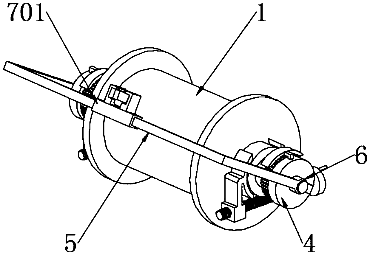
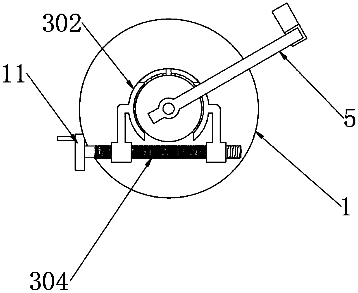
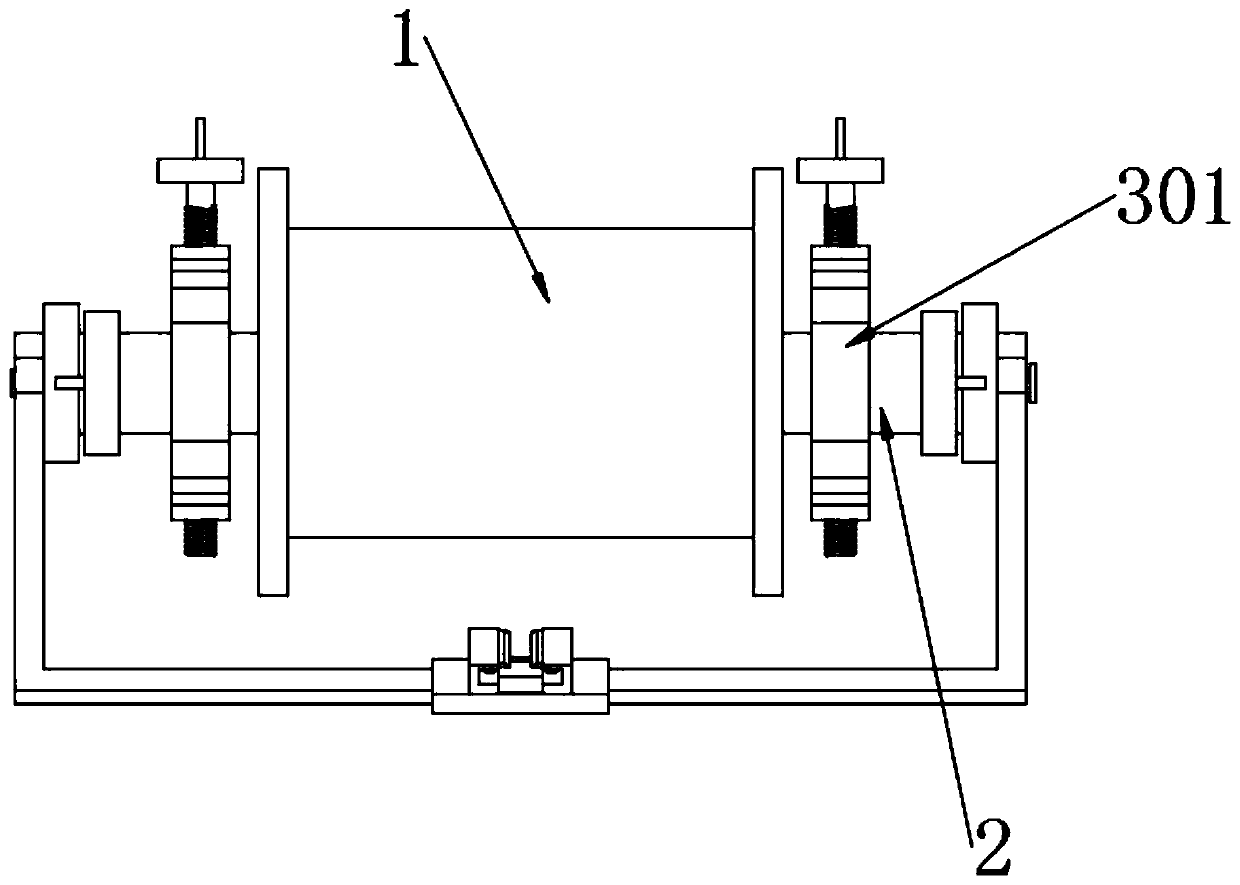
[0031] Example: such as Figure 1-4 As shown, the present invention provides a technical solution, a mechanical damping passive pay-off device, comprising a pay-off wheel 1 and a central axis 2 located at the center of the pay-off wheel 1 and passing through the pay-off wheel 1, both sides of the central axis 2 are A damping mechanism 3 is provided, and the damping mechanism 3 includes a turntable 301, a damping plate 302, a connecting rod 303, a screw rod 304, and a screw nut 305. Both ends of the central shaft 2 are sleeved with a turntable 301 near the end surface of the pay-off wheel 1, and the turntable Both sides of 301 are provided with damping sheet 302, and...


PUM


Abstract

The invention discloses a mechanical damping passive pay-off unit. The mechanical damping passive pay-off unit comprises a pay-off wheel and a center shaft, wherein the center shaft is located in thecenter of the pay-off wheel and penetrates through the pay-off wheel. Damping mechanisms are arranged on the two sides of the center shaft respectively. The mechanical damping passive pay-off unit isscientific and reasonable in structure, and safe and convenient to use; because of the damping mechanisms, friction is generated through contact between each damping fin and the corresponding rotary plate, the pay-off speed of the pay-off wheel can be controlled, and the pay-off wheel can carry out pay-off work stably; because of connecting rods, lead screws, threaded rods and nuts, the separationdistance between each threaded rod and the corresponding nut is adjusted by turning the corresponding lead screw to adjust the gluing force between the corresponding damping fin and the correspondingrotary plate, then friction is changed to achieve the effect of having control over the rotating speed of the pay-off wheel, pay-off is smooth and steady, and the tension of cables is kept as well; and because adjusting gears are driven by rotary shafts to rotate, then racks are driven to move upwards or downwards to enable each positioning toothed plate and the corresponding gear to be separatedor be in engagement connection, the gears can rotate freely when each positioning toothed plate and the corresponding gear are separated, and when each positioning toothed plate and the correspondinggear are separated, the gears are locked, the pay-off wheel is locked as well, and the mechanical damping passive pay-off unit is more convenient to use.

Description

technical field [0001] The invention relates to the technical field of pay-off devices, in particular to a passive pay-off device with mechanical damping. Background technique [0002] With the continuous development of the economy, more and more places assume that the cable is used for power information transmission. In the cable laying work, a cable pay-off device is needed. The traditional cable pay-off device uses an I-shaped wheel. The pay-off power of the I-shaped wheel is realized by the power of the wire drawing machine. Since the I-shaped wheel has a large resistance due to its own weight, the resistance decreases continuously from the full shaft to the empty shaft when the I-shaped wheel pays off. , so that the dynamic tension from large to small is generated during the pay-off process, which affects the stability of the pay-off, and the cable is easy to move back and forth when the pay-off is too long, which affects the pay-off work, so a mechanical damping passiv...

Claims


Application Information

Patent Timeline
Patent Type & Authority Applications(China)
IPC IPC(8): B65H59/04
CPCB65H59/04B65H2701/34
Inventor 王若昆
Owner NANJING INST OF RAILWAY TECH
Why Eureka
Try Eureka