Vibration spring humidifying electric fan and use method thereof

An electric fan and fan technology, applied in heating methods, air humidification systems, applications, etc., can solve the problems of complex structure, high cost, unfavorable miniaturization, etc., and achieve good dust removal effect, improve cooling effect, and improve the effect of humidifying effect.

Active Publication Date: 2020-01-03
佛山市信孚进出口有限公司
View PDF6 Cites 11 Cited by
  • Summary
  • Abstract
  • Description
  • Claims
  • Application Information

AI Technical Summary

Problems solved by technology

[0003] During the use of the electric fan, the effect of cooling and heat dissipation is achieved by accelerating the air circulation, but when the surrounding air temperature is high, the heat dissipation effect of the electric fan will be greatly reduced, and the existing fans with humidification function generally use The combination of atomizer or humidifier and electric fan, this kind of fan is not only expensive, it is difficult to be accepted by ordinary users, but also the structure is more complicated after integrating the atomizer or humidifier, which is not conducive to the miniaturization of the volume, so the use of occasions are very limited

Method used


Image

  • Vibration spring humidifying electric fan and use method thereof
  • Vibration spring humidifying electric fan and use method thereof

Examples


Embodiment 1

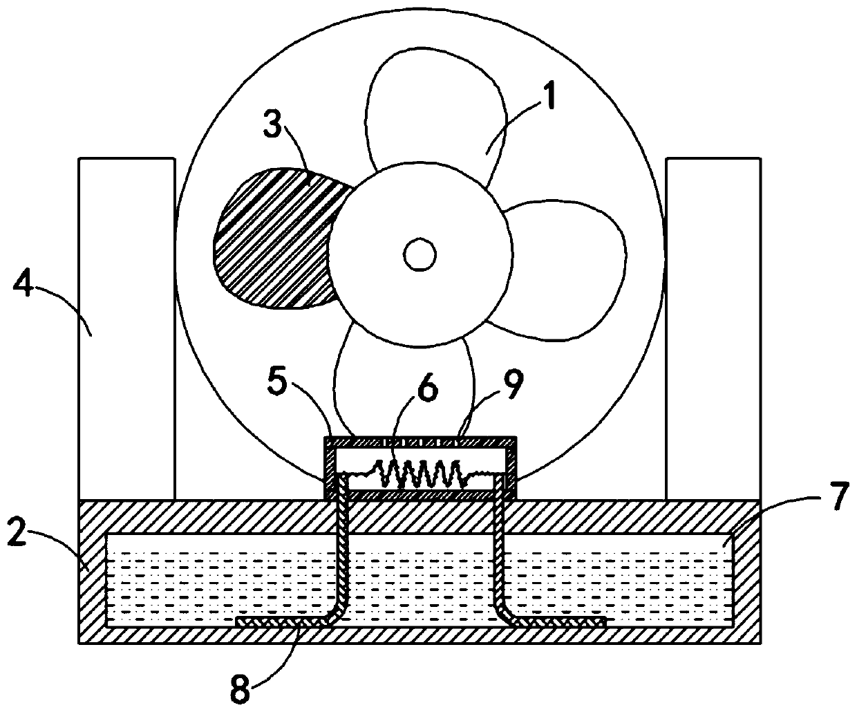
[0017] Such as figure 1 As shown, a vibrating spring humidifying electric fan includes a fan body 1 and a base 2. The fan body 1 adopts a waterproof motor, and the number of blades of the fan body 1 can be set to 3 to 5, and one of the blades of the fan body 1 3 Using permanent magnet material, both sides of the upper end of the base 2 are fixedly connected with support columns 4, the fan body 1 is fixedly connected between the two support columns 4, the rear side of the fan body 1 is provided with a humidification box 5, inside the humidification box 5 A vibrating spring 6 is provided. The two ends of the vibrating spring 6 are respectively fixedly connected to the left and right inner side walls of the humidification box 5, and the surface of the vibrating spring 6 is fixedly connected with absorbent velvet. The base 2 is provided with a liquid storage chamber 7, and the liquid storage chamber 7 and There is a water guide hole between the humidification box 5, and a water abso...

Embodiment 2

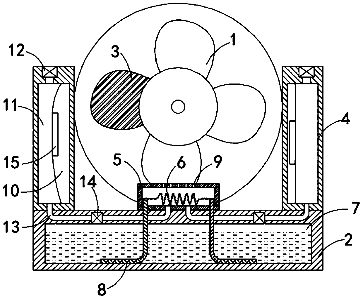
[0022] Such as figure 2 As shown, the difference between this embodiment and embodiment 1 is that the support column 4 is provided with a cavity 10, and an elastic airbag 11 is fixedly connected to the cavity 10. The elastic airbag 11 can be made of silicone material, and the upper end of the elastic airbag 11 An intake valve 12 communicating with the outside is provided. The lower end of the elastic airbag 11 is connected to the humidification box 5 through an exhaust passage 13, and an exhaust valve 14 is fixedly connected to the exhaust passage 13. It should be noted that the exhaust passage The exhaust port of 13 is located directly below the water-permeable hole 9 to improve the spraying effect of small water droplets. The two elastic airbags 11 are fixedly connected to the opposite sidewalls with permanent magnet sheets 15, and the permanent magnet sheets 15 are connected with permanent magnets. The fan blades 3 of the material repel with each other.

[0023] In this embo...


PUM


Abstract

The invention belongs to the field of fans and particularly relates to a vibration spring humidifying electric fan and a use method of the vibration spring humidifying electric fan. The electric fan comprises a fan body and a base. One of fan blades of the fan body adopts a permanent magnet material. The two sides of the upper end of the base are fixedly connected with support columns correspondingly. The fan body is fixedly connected between the two support columns. A humidifying box is arranged on the rear side of the fan body. A vibration spring is arranged in the humidifying box. The two ends of the vibration spring are fixedly connected with the left inner side wall and the right inner side wall of the humidifying box correspondingly. A fuzzy water absorbing part is fixedly connectedto the surface of the vibration spring. A liquid storage cavity is formed in the base. Water guide holes are formed between the liquid storage cavity and the humidifying box. Water absorbing strips are arranged in the water guide holes. The lower ends of the water absorbing strips are located in the liquid storage cavity. The upper ends of the water absorbing strips are fixedly connected with thevibration spring. Water permeable holes are densely formed in the upper end of the humidifying box. By the adoption of the vibration spring humidifying electric fan and the use method, the magnetic fan blades can be used to drive the vibration spring to vibrate, and therefore the humidifying effect can be achieved.

Description

[0001] This application is a divisional application for a vibrating spring humidifying electric fan with the application date of July 18, 2018, and the application number is CN201810786947.8. Technical field [0002] The invention belongs to the field of fans, and in particular relates to a vibrating spring humidifying electric fan and a use method thereof. Background technique [0003] During use, the electric fan accelerates air circulation to achieve the effect of cooling and heat dissipation. However, when the surrounding air temperature is high, the heat dissipation effect of the electric fan will be greatly reduced, while the existing fans with humidification function generally use The combination of an atomizer or humidifier and an electric fan. This fan is not only expensive and difficult to be accepted by ordinary users, but also has a complicated structure after the atomizer or humidifier is integrated, which is disadvantageous to miniaturization of the volume. The occas...

Claims


Application Information

Patent Timeline
Patent Type & Authority Applications(China)
IPC IPC(8): F04D25/08F04D29/00F04D29/02F04D29/38F04D29/70F24F6/12
CPCF04D25/08F04D29/002F04D29/023F04D29/38F04D29/703F24F6/12
Inventor 张志华
Owner 佛山市信孚进出口有限公司
Why Eureka
Try Eureka