Supercharge Your Innovation With Domain-Expert AI Agents!

Electrical metering and switching equipment

A technology of switchgear and electrical metering, applied in substation/switch layout details, electrical components, substation/switchgear board/panel/desk, etc., can solve problems such as unusable

Inactive Publication Date: 2020-01-03
江苏长易电气有限公司
View PDF0 Cites 0 Cited by
  • Summary
  • Abstract
  • Description
  • Claims
  • Application Information

AI Technical Summary

Problems solved by technology

[0004] In other words, the internal layout and dimensions of the existing equipment are related to the requirements of the local power company and cannot be used in other places

Method used


Image

  • Electrical metering and switching equipment
  • Electrical metering and switching equipment
  • Electrical metering and switching equipment

Examples


Embodiment Construction

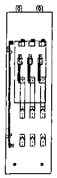
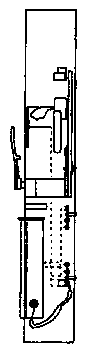
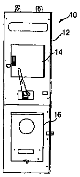
[0020] First refer to Figure 1 to Figure 4 . refer to Figures 1A-1D , a typical prior art assembly 10 includes a device for accommodating two (in Figure 3C Cabinet 12 : instrumentation 14 and three-phase disconnect switch 16 , best seen in . The relative position of these two devices depends on two factors: the entry point of the input (line) cable and the voltage of the line. like Figure 1A -D shows that the input cables are connected from the top and the output cables (into the load) are connected at the bottom. For low voltage lines (typically below 480vac), meter 14 is on the line side. For high voltage lines, the switch is on the line side. Switch 16 is commonly referred to as a miniature stud pressure switch, such as those manufactured by Bolt Switch Company of Crystal Lake, Illinois, with appropriate amperage and voltage ratings.

[0021] Of particular interest to this class of equipment is the cabling, more specifically the input cabling. The problem with th...


PUM


Abstract

The invention discloses electrical metering and switching equipment, which comprises a cabinet. The cabinet is provided with two parts which are respectively used for fixing an instrument panel and aswitch. The switch is preferably an HCP switch. The part holding the instrument panel comprises a subassembly. The subassembly comprises two horizontal plates and a plurality of buses passing throughthe plates and suitable for providing connections with current and voltage transformers of the instrument panel.

Description

technical field [0001] The present invention relates to a novel metering and switching device which can be used to control and meter three-phase lines with different voltage and current characteristics meeting UL standards. Background technique [0002] Various national and local electrical codes, as well as standard practice, state that the power lines (whether single-phase or multi-phase) that supply a site or building must first be connected to service equipment that provides power metering and, optionally, control switching. Typically, the service equipment comprises a generally vertical metal cabinet with an entry point at the bottom receiving incoming conductors and an exit point at the top through which the conductors exit. Between the entry and exit points, terminations are provided for the conductors, which are then interconnected either directly through copper bars or through overcurrent protection. Standard current and voltage transformers are also provided for m...

Claims


Application Information

Patent Timeline
Patent Type & Authority Applications(China)
IPC IPC(8): H02B1/04H02B1/30H02B1/32H02B1/20
CPCH02B1/04H02B1/20H02B1/30H02B1/32
Inventor 宋贺
Owner 江苏长易电气有限公司
Features
  • R&D
  • Intellectual Property
  • Life Sciences
  • Materials
  • Tech Scout
  • Unparalleled Data Quality
  • Higher Quality Content
  • 60% Fewer Hallucinations
Learn More